10.1 Purpose and Scope
A disciplined design process converts user requirements into constructible, code-compliant, and maintainable OSP infrastructure. Documentation is both the product of that process and the permanent record that supports construction, operations, maintenance, and future expansion. Incomplete or inaccurate documentation is a leading cause of field conflicts, change orders, and long-term operational problems.
This chapter outlines the professional design process and the documentation deliverables expected of an RCDD, OSP Designer, ICT consultant, or telecommunications engineer. Guidance is aligned with the BICSI Outside Plant Design Reference Manual (OSPDRM) 6th Edition, the BICSI G-series standards, ASCE/UESI/CI 38-22, and current industry practice for campus, carrier, utility, and government networks as of 2026.
10.2 Design Process Overview
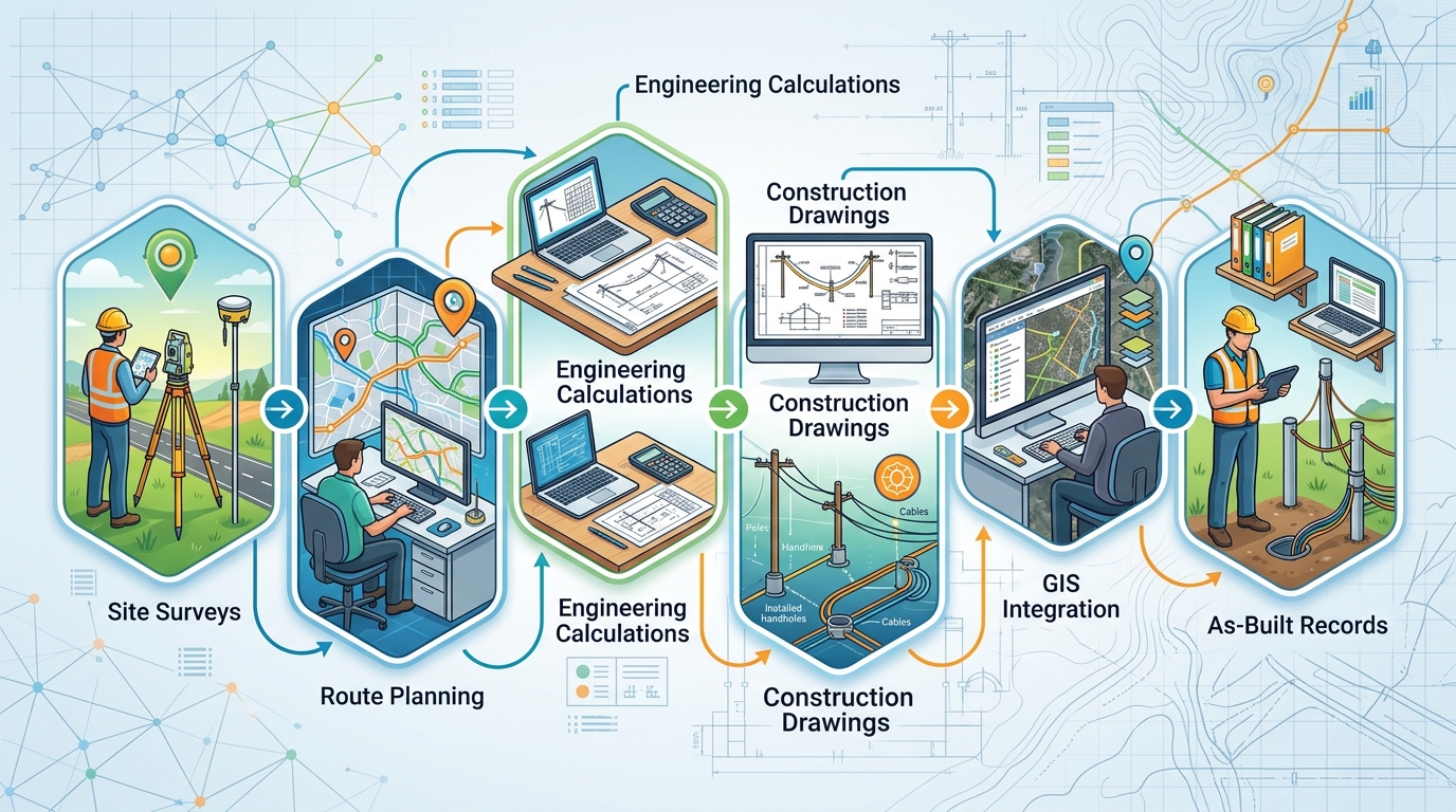
A structured OSP design process typically includes the following phases:
- Requirements Definition Clarify performance objectives, capacity needs, reliability targets, budget, schedule, security requirements, and constraints imposed by the owner or AHJs.
- Existing-Conditions Assessment Collect and verify data on existing pathways, cables, structures, utilities, right-of-way, and environmental conditions.
- Route Selection and Alternatives Analysis Evaluate candidate routes against technical, legal, environmental, cost, and constructability criteria. Document the basis for the preferred alternative.
- Detailed Design Develop pathway, space, media, bonding/grounding, and transition details. Perform required calculations (loading, clearances, pull tension, capacity, optical budgets).
- Review and Coordination Circulate design packages for internal, owner, utility, and AHJ review. Resolve comments and obtain necessary approvals.
- Construction Support Respond to RFIs, review shop drawings and material submittals, and support field changes.
- As-Built and Close-Out Verify installed conditions, update documentation, and transfer records to the owner.
10.3 Site Surveys and Data Collection
Accurate field data is the foundation of sound design. Surveys should capture:
- Topography, surface features, and existing structures
- Visible and subsurface utilities
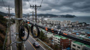
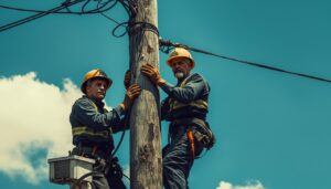
- Existing poles, anchors, guys, and attachment space
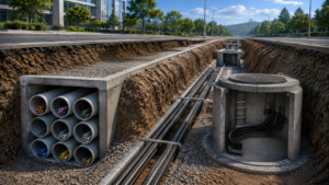
- Manholes, handholes, and vaults (including interior condition and available capacity)
- Building entrance locations and conditions
- Environmental constraints (wetlands, trees, slopes, flood zones)
- Photographs and GPS coordinates
Survey notes and photographs should be organized and retained as part of the project record.
10.4 Subsurface Utility Engineering and Existing Utility Investigation
Accurate knowledge of existing underground utilities is essential for sound OSP route selection, conflict avoidance, and constructability. Incomplete or unreliable utility information is a leading cause of redesign, delays, damage, and claims.
Subsurface Utility Engineering (SUE) provides a standardized, risk-based method for investigating and documenting existing utilities. The governing standard is ASCE/UESI/CI 38-22, Standard Guideline for Investigating and Documenting Existing Utilities.
Utility Quality Levels
ASCE 38-22 defines four Quality Levels that indicate the reliability of depicted utility data:
- Quality Level D – Information derived solely from existing records or oral recollections. Suitable only for early planning.
- Quality Level C – Survey of visible surface features correlated with records.
- Quality Level B – Horizontal position determined by surface geophysical methods (electromagnetic locators, ground-penetrating radar, etc.) and surveyed to project control. This is the most commonly applied design-level investigation.
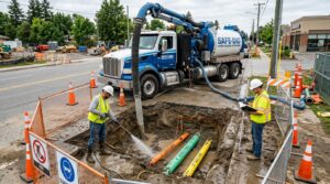
- Quality Level A – Precise horizontal and vertical location obtained by physical exposure (normally vacuum excavation) and surveyed to project control. Provides the highest reliability.
Vacuum Excavation (Soft Digging)
Vacuum excavation (hydro or air methods) is the preferred technique for achieving Quality Level A data. It uses high-volume vacuum combined with pressurized water or air to expose utilities with minimal risk of damage. The method allows visual confirmation of utility size, material, condition, and exact three-dimensional position.
Risk-Based Application
A full QL-A investigation of every utility is rarely necessary or cost-effective. Professional practice applies QL-B across the corridor and selectively advances to QL-A at locations where:
- The proposed pathway crosses or closely approaches existing utilities
- Vertical clearance is critical
- Congestion or poor records increase uncertainty
- The consequences of conflict are high (critical fiber routes, utility operational circuits, government networks, etc.)
Documentation and Specifications
SUE data must be clearly depicted on design drawings with the applicable Quality Level noted. Specifications should reference ASCE 38-22, define required accuracy, and state restoration requirements for test holes. Final as-built records should incorporate confirmed utility information for future reference.
When properly scoped and executed, SUE significantly reduces construction risk and supports the reliable, conflict-minimized OSP designs expected on campus, carrier, utility, and government projects.
10.5 Calculations and Engineering Analysis
Depending on the pathway type, the Designer performs or directs:
- Aerial structure loading and strength checks (NESC)
- Clearance verification
- Conduit fill and pulling-tension / sidewall-pressure calculations
- Optical link budgets
- Capacity and spare-duct analysis
- Bonding and grounding continuity assessments
All calculations should be documented with assumptions, references, and results so they can be reviewed and reused.
10.6 Design Deliverables
Professional OSP design packages commonly include:
- Cover sheet with project identification, location map, and drawing index
- General notes, abbreviations, and references to applicable codes and standards
- Plan drawings showing routes, pathway types, and major features
- Profile or section drawings where elevation changes or conflicts are significant
- Typical details (trench, duct bank, pole attachment, manhole, transition, grounding)
- Pole schedules or structure lists
- Cable schedules (type, count, length, reel assignments)
- Bill of materials or material specifications
- Right-of-way and permit exhibits
- Calculations package (as needed)
- Utility investigation results with Quality Level designations
Drawings should be prepared to a professional standard of clarity and completeness suitable for competitive bidding and construction.
10.7 Geographic Information Systems (GIS) Integration
Modern OSP design increasingly incorporates GIS. Route alignment, existing utility data, environmental layers, and as-built information are commonly managed in GIS environments. Final as-built records should be delivered in a format compatible with the owner’s GIS or asset-management system. Coordinate systems, accuracy standards, and attribute requirements must be agreed upon early.
10.8 Construction Documents and Specifications
Design drawings are typically accompanied by written specifications that define materials, installation methods, testing, and quality requirements. Specifications should reference the appropriate BICSI G-series standards, NESC, ASCE 38-22 (when SUE is required), and manufacturer requirements. Clear division of responsibility between designer, constructor, and owner reduces disputes.
10.9 As-Built Documentation
As-built (record) drawings and data must reflect the final installed condition, including:
- Actual cable routes and lengths
- Splice and slack storage locations
- Final pole attachment heights and configurations
- Manhole/handhole contents and cable assignments
- Measured test results
- Confirmed existing utility information obtained through SUE
- Any deviations from the original design
Accurate as-builts are essential for future maintenance, restoration, and capacity planning. Many owners now require GIS-compatible digital deliverables in addition to traditional drawings.
10.10 Quality Control and Professional Responsibility
The OSP Designer is responsible for the technical adequacy of the design within the defined scope. A structured quality-control review—checking completeness, code compliance, coordination with other disciplines, utility conflict resolution, and constructability—should be performed before issuance. On complex projects, independent peer review is recommended.
10.11 Application Notes by Network Type
Campus — Emphasis on coordination with architectural, civil, and landscape disciplines and on aesthetic restoration details. SUE is particularly valuable in mature campuses with dense, poorly documented utilities. Carrier — High volume of standardized details, rigorous cable and splice documentation, long-route GIS management, and selective QL-A at critical crossings. Utility — Integration with existing utility mapping systems and strict adherence to company drafting and data standards. Government — Compliance with agency-specific drawing standards, security classification requirements, formal review cycles, and often elevated SUE requirements for critical infrastructure.
10.12 Summary
A systematic design process supported by thorough field data, appropriate subsurface utility investigation, rigorous analysis, and complete documentation produces OSP infrastructure that can be constructed efficiently and operated reliably for decades. The RCDD or OSP Designer must treat documentation—and the quality of the utility data that underlies it—as a core professional deliverable equal in importance to the physical design itself.
Frequently Asked Questions – Outside Plant (OSP) Design & Subsurface Utility Engineering
What is Outside Plant (OSP) in telecommunications? Outside Plant (OSP) refers to all telecommunications infrastructure located outside of buildings, including aerial, underground, and direct-buried cables, conduits, manholes, poles, and related support structures. It forms the backbone that connects campuses, carrier networks, utilities, and government facilities.
What is Subsurface Utility Engineering (SUE)? Subsurface Utility Engineering is a specialized engineering practice used to investigate, map, and document existing underground utilities. It follows the ASCE 38-22 standard and assigns Quality Levels (QL-D through QL-A) that indicate how reliable the utility location data is.
What are the ASCE 38 Quality Levels?
- QL-D: Based only on existing records
- QL-C: Records plus survey of visible surface features
- QL-B: Geophysical designation (electromagnetic locators and ground-penetrating radar)
- QL-A: Physical exposure using vacuum excavation for precise horizontal and vertical location
What is vacuum excavation (soft digging)? Vacuum excavation is a non-destructive method that uses high-powered vacuum combined with water (hydro-excavation) or air to safely expose buried utilities. It is the primary technique for achieving ASCE 38 Quality Level A data and greatly reduces the risk of damaging fiber, conduit, or other utilities.
When should Quality Level A (vacuum excavation) be used on an OSP project? QL-A is recommended at critical utility crossings, locations with limited vertical clearance, congested urban or campus corridors, and anywhere the consequences of a utility strike are high. Most projects use QL-B across the route and selectively apply QL-A only where needed.
Why is SUE important for OSP designers and RCDDs? Inaccurate utility information is one of the leading causes of redesigns, construction delays, cable damage, and cost overruns. Professional use of SUE improves route selection, reduces risk, supports better documentation, and leads to more constructible designs.
What standards govern OSP design and construction in 2026? Key references include the BICSI Outside Plant Design Reference Manual (OSPDRM) 6th Edition, BICSI G-series standards (G1, G2.1-22, G2.2-22, G3-2026, G4-23), IEEE C2-2023 (NESC), ASCE 38-22 for utility investigation, and applicable TIA standards.
How does SUE fit into the OSP design process? SUE is performed during the existing-conditions assessment phase. Results are shown on design drawings with the appropriate Quality Level designation and are used to avoid conflicts, refine routes, and produce more accurate construction documents and as-builts.
Is vacuum excavation required on every OSP project? No. It is applied on a risk-based basis. Simple rural routes with good records may need little or no QL-A work, while complex campus, urban, or critical-infrastructure projects typically benefit from selective vacuum excavation.
Where can I learn more about professional OSP design? Authoritative sources include the BICSI Outside Plant Design Reference Manual (OSPDRM), BICSI OSP Design credential training, ASCE 38-22, and current editions of the National Electrical Safety Code (NESC).