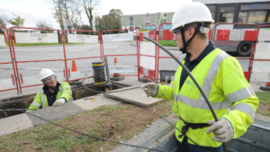
What is lead-in cabling?
Lead-in cabling is the cabling from the last distribution point in a carrier’s telecommunications network to the “network boundary”, e.g. a Network Termination Device (NTD) in a customer’s premises.
Lead-in cabling will normally be installed underground unless aerial cabling distribution is already being used in the street and/or the ground conditions or circumstances preclude underground installation.
Telecommunications carriers decide whether to install their lead-in cabling underground or aerial based on technical, safety, economic and any applicable environmental or regulatory factors. Underground cabling is used in virtually all new property developments.
Where underground lead-in cabling is to be installed, the builder, home owner or customer is required to arrange and pay for suitable trenching for the lead-in cabling between the carrier’s cabling entry point at the boundary of the premises (“property entry point”) and the cabling entry point at the building (“building entry point”).
“Trenching” means clearing of land along the cabling route, digging of the trench and reinstating the land after the cabling is installed.
The builder, owner or customer may also be required to supply and install the lead-in conduit. In urban areas, lead-in cabling is installed in conduit irrespective of the distance between the property boundary and the building.
Where the total length of the conduit will exceed 50 m, intermediate pits are required at no more than 50 m intervals to provide access points for pulling cables.
Conduit material and size
For an individual home, the lead-in conduit must be rigid UPVC with an inside diameter (ID) of 23 mm. Flexible or corrugated conduit must not be used for underground lead-in cabling. Lead-in conduit and bends must be coloured white. Conduit of any other colour is not acceptable.
Bends and curves
No more than two underground 90° bends with a minimum inner bend radius of 300 mm are permitted between access points. A third 90° bend with a minimum inner bend radius of 100 mm is permitted above ground at the cable access point at the building (e.g. in the wall cavity). Only prefabricated bends may be used.
Conduits must not be bent on site (e.g. by application of heat).
Curvature of glued lengths of conduit is allowable without affecting the number of bends that may be used as long as the curvature radius is no less than 130 times the nominal inside diameter of the conduit (in practical terms, this means curving the conduit without distorting the cross-sectional roundness of the conduit).
Where it would be necessary to use more than two underground 90° bends (e.g. to effect a sharp change of direction in the middle of the conduit run), an intermediate access pit must be used as a cable pulling point.
Conduit Installation
Conduit and bend joints must be glued with solvent cement. The conduit markings should face upwards when the conduit is laid in the trench so as to be visible if the conduit is exposed by digging after its initial installation.
A pull-cord or cable must be threaded through the lengths of conduit during assembly for later installation of the lead-in cable by the carrier. Each end of the conduit must be plugged to prevent the ingress of silt or debris into the conduit.
Use of lead-in conduits/pits/cables
Lead-in conduit must not be used for customer cabling (e.g. for private cabling to another building in the premises). Customer cabling must be installed in separate conduit but may share the lead-in trench. Separate conduit must be provided for the installation of customer cabling between buildings.
Lead-in pits should not be used for customer cabling unless this is unavoidable (e.g. due to limited space for locating pits), in which case only lead-in pits supplied and installed by the builder, owner or customer may be shared with customer cabling.
In such cases, the customer cabling must be clearly labeled in the pit. Lead-in pits installed by the carrier (i.e. with the carrier’s markings) must not be used for customer cabling.
Property entry point
The property entry point is the point where the carrier’s lead-in cabling will enter the private land in which the building is located, including
- any land occupied in common with, or shared with, multiple occupants (e.g. land controlled by a body
corporate); and - any private easement or right of way (e.g. a driveway).
The carrier determines the location of the property entry point based on the location of the nearest suitable lead-in cable connection point. Where radio technology is used to supply a service to the premises, the property entry point is the base of the radio shelter or antenna structure from which the cabling runs to the building.

