4.1 Purpose and Scope
Underground pathways provide the highest level of mechanical protection and long-term reliability for OSP cabling in campus, carrier, utility, and government networks. When properly designed and constructed, they minimize exposure to weather, vehicles, vandalism, and accidental damage while facilitating future cable placement and maintenance.
This chapter addresses the design and construction of underground OSP pathways and associated spaces in accordance with BICSI G3-2026 (ICT Outside Plant Construction and Installation: Underground Facilities and Pathways – General Practices), the Outside Plant Design Reference Manual (OSPDRM) 6th Edition, ANSI/TIA-758-B, IEEE C2-2023 (NESC), and related industry practices. It covers duct banks, conduits, manholes, handholes, vaults, innerduct systems, placement methods (including directional boring), and protection requirements.
The guidance is written for professional application by RCDDs, OSP Designers, ICT consultants, and telecommunications engineers responsible for permanent infrastructure assets.
4.2 Design Objectives
Underground pathway design must achieve the following objectives:
- Adequate capacity for the initial cable complement plus planned growth (typically 50–100 % spare duct capacity on backbone routes).
- Mechanical and environmental protection consistent with the criticality of the served network.
- Accessibility for installation, splicing, testing, and restoration throughout the expected service life (commonly 30–50 years or more).
- Compliance with NESC underground rules, local excavation and right-of-way requirements, and environmental regulations.
- Compatibility with building entrance facilities and transitions to aerial or direct-buried segments.
- Minimization of future surface disruption, particularly under roadways, railways, and finished campus or government landscapes.
4.3 Conduit and Duct Bank Systems
Materials Common conduit materials include rigid PVC (Schedule 40 or 80), high-density polyethylene (HDPE), rigid metal conduit (RMC), and intermediate metal conduit (IMC). Selection is driven by soil conditions, expected loading, chemical exposure, and AHJ requirements. Non-metallic conduits predominate in most telecommunications applications because of corrosion resistance and dielectric properties.
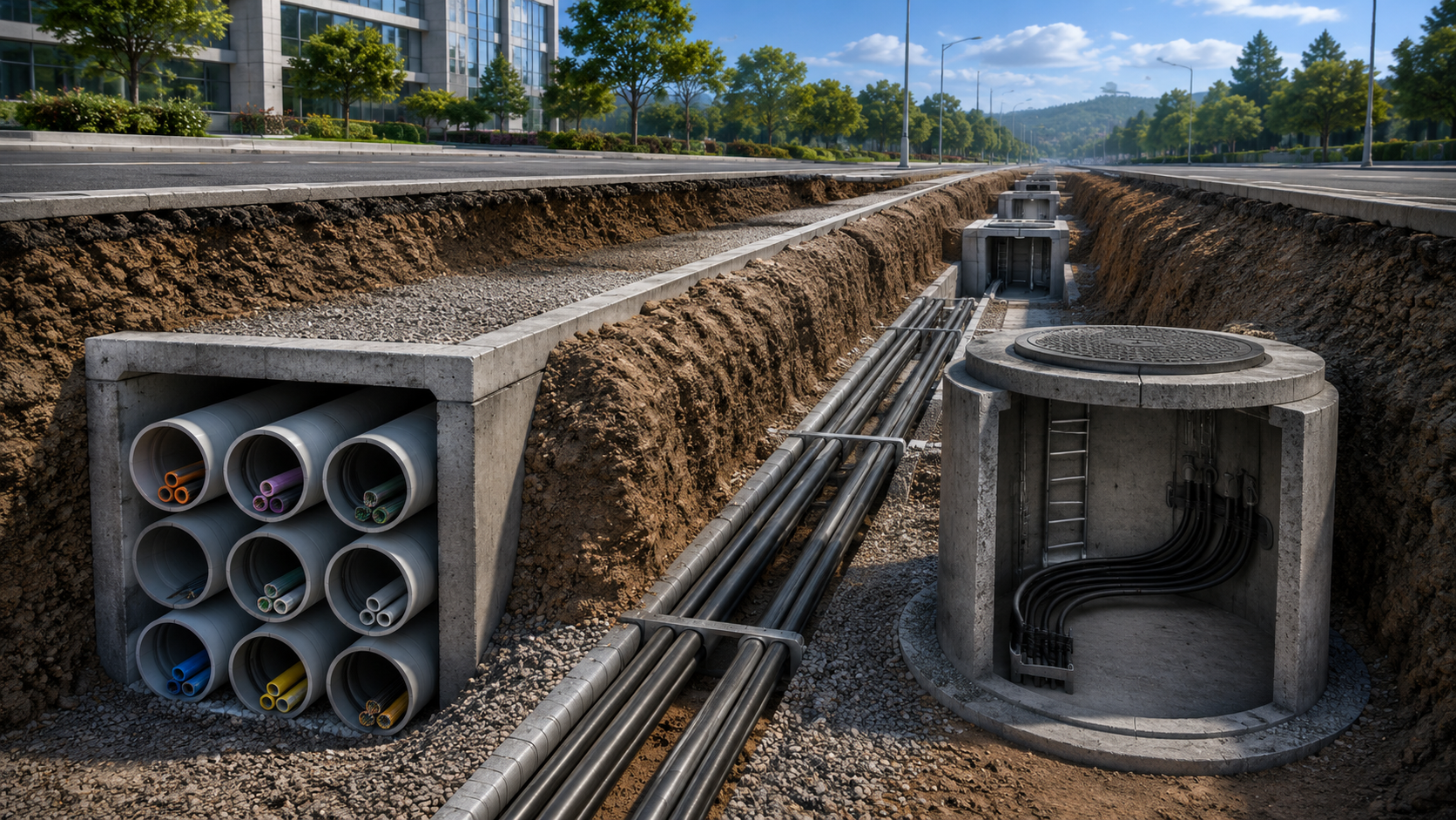
Configuration Duct banks are typically arranged in multi-duct formations (e.g., 2×2, 3×3, 4×4, or larger) encased in concrete or direct-buried. Concrete encasement provides superior protection against excavation damage and is preferred under roadways, railways, and high-traffic areas. Direct-buried multi-duct systems are acceptable in lower-risk corridors when properly marked and bedded.
Sizing and Fill Conduit trade sizes commonly range from 1¼ in to 4 in or larger. Maximum recommended fill for multiple cables is generally 40 % of the internal cross-sectional area, subject to manufacturer data and pulling-tension calculations. Spare ducts should be provided and sealed. Innerduct or sub-duct systems are routinely installed within larger conduits to increase usable capacity and facilitate future cable placement by air-assisted or conventional pulling methods.
Separation and Depth Minimum cover and separation from other utilities are governed by NESC Rule 352, local codes, and project specifications. Typical minimum cover is 24 in (600 mm) in non-traffic areas and 36 in (900 mm) or greater under roadways, adjusted for frost depth, soil conditions, and local requirements. Separation from power ducts must satisfy both NESC and induction-mitigation criteria, particularly in utility corridors.
4.4 Manholes, Handholes, and Vaults
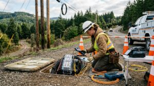
Function and Placement Access spaces are required at changes in direction, elevation, cable transitions, and at intervals that keep pulling lengths within safe tension and sidewall-pressure limits (typically 300–600 ft / 90–180 m depending on cable type and route geometry). Placement must also consider future maintenance access and traffic loading.
Sizing Interior dimensions must accommodate the planned number of cables, splice closures, slack storage (often 15–30 ft / 5–10 m per cable), working clearances, and future growth. Standard telecommunications manholes range from approximately 4×6×4 ft to larger multi-bay structures. Handholes are used for lighter-duty applications and lower cable counts.
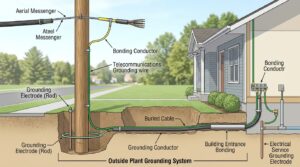
Structural and Environmental Requirements Structures must be rated for the anticipated traffic or soil loading (H-20 or higher under roadways). Drainage, sump provisions, and corrosion-resistant materials are essential. Bonding and grounding of metallic components, racks, and cable shields must comply with NESC and BICSI requirements. In government and high-security applications, locking covers, intrusion detection, and controlled access may be required.
Special Vaults Controlled-environment vaults (CEVs) or larger equipment vaults are used when active electronics or extensive splicing is required. These spaces introduce additional requirements for power, HVAC, fire protection, and security.
4.5 Placement Methods
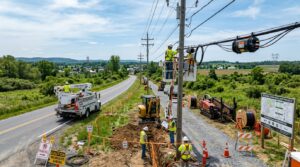
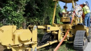
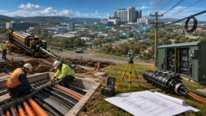
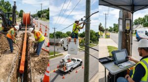
Open-Cut Trenching Traditional excavation remains common for duct-bank construction in undeveloped or easily restored corridors. Proper bedding, shading, and backfill compaction are critical to long-term performance.
Directional Boring (Horizontal Directional Drilling) Preferred for crossings of roadways, railways, waterways, and finished surfaces. Bore path design must account for bend radius limitations of both the conduit and the eventual cable, soil conditions, and existing utility conflicts. Accurate locating and as-built documentation of the bore path are mandatory.
Other Methods Micro-trenching, plowing (for limited applications), and pipe-jacking are used selectively according to site constraints and local acceptance.
All methods require strict adherence to one-call (811) procedures, utility coordination, and excavation safety regulations (OSHA).
4.6 Protection Systems
- Warning tape or detectable marking tape installed above the duct bank.
- Electronic marker balls or continuous tracer wire for future locating.
- Concrete encasement or steel casing at high-risk crossings.
- End seals, duct plugs, and water-blocking measures to prevent moisture and rodent intrusion.
- Cathodic protection where metallic conduits are used in corrosive soils.
4.7 Transitions and Interfaces
Transitions between underground and aerial or direct-buried segments require carefully detailed riser poles, pedestal terminations, or building entrance arrangements. Building entrances must satisfy NEC length limitations on unlisted OSP cable, firestopping, bonding continuity, and physical protection. Coordination with the premises cabling designer is essential.
4.8 Documentation and Quality Assurance
Design documents must include plan and profile drawings, duct-bank cross-sections, manhole/handhole details, capacity calculations, and material specifications. Construction quality assurance includes verification of depth, alignment, mandrel testing of conduits, pressure testing where required, and complete as-built records (preferably in GIS-compatible format). Acceptance testing of installed pathways precedes cable placement.
4.9 Application Notes by Network Type
Campus — Emphasis on spare capacity, aesthetic restoration, and coordination with landscape and civil works. Concrete-encased duct banks under primary roadways are common.
Carrier — High duct counts, frequent access points, and rigorous documentation to support rapid restoration and future fiber adds.
Utility — Strict separation from power facilities, induction mitigation, and compliance with utility-specific standards in addition to NESC.
Government — Enhanced physical security, possible PDS requirements, and multi-agency review of pathway routes and access controls.
4.10 Summary
Underground pathways represent a significant capital investment whose performance determines the reliability and expandability of the OSP network for decades. Design in accordance with BICSI G3-2026 and supporting standards, combined with disciplined capacity planning and thorough documentation, produces infrastructure that meets the demanding requirements of modern campus, carrier, utility, and government applications.
Detailed construction methods, material specifications, and acceptance criteria are further developed in the installation-focused portions of the BICSI G-series and should be incorporated by reference into project specifications.