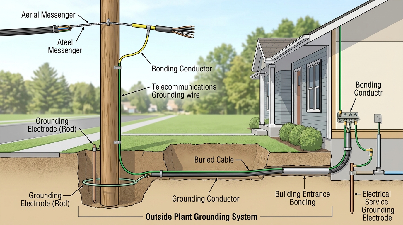
8.1 Purpose and Scope
Proper bonding, grounding, and electrical protection are essential for personnel safety, equipment protection, and reliable network performance in outside plant environments. OSP facilities are exposed to lightning, power faults, induction from adjacent power lines, and ground-potential differences. Inadequate practices can result in equipment damage, service outages, or injury.
This chapter addresses OSP-specific requirements drawn from IEEE C2-2023 (National Electrical Safety Code), ANSI/BICSI N3-20, the BICSI Outside Plant Design Reference Manual (OSPDRM) 6th Edition, the BICSI G-series standards, and related industry guidance current as of 2026. It covers aerial, underground, and direct-buried applications as well as interfaces with building entrance facilities.
8.2 Fundamental Principles
Bonding creates low-impedance electrical connections between metallic components so that they remain at substantially the same potential. Grounding connects the bonded system to earth. In OSP, the objectives are:
- To limit voltage differences that could endanger workers or damage equipment.
- To provide a path for fault and surge currents.
- To reduce inductive coupling and noise.
- To satisfy NESC and local code requirements.
All-dielectric designs (ADSS, non-metallic messengers, non-metallic strength members) eliminate many bonding requirements and are preferred near high-voltage power facilities when practical.
8.3 Aerial Systems
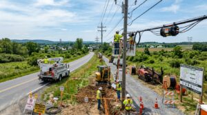
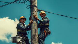
Messengers and Guys Metallic messengers supporting lashed cable must be bonded and grounded in accordance with NESC rules (particularly Rules 092, 097, and 215). The 2023 NESC extends previous bonding requirements for communications messengers to include all messengers, supply neutrals, and metallic poles under Rule 215D.
Common practice includes:
- Bonding the messenger to the pole ground at regular intervals (often every pole or as required by the joint-use agreement and NESC multi-grounded system criteria).
- Bonding multiple messengers together where they share a structure.
- Ensuring guys are either effectively grounded or insulated as required by NESC Rule 215C and 279.
Joint-Use Considerations On joint-use poles the communications messenger is typically bonded to the multi-grounded neutral system. Coordination with the power utility is mandatory. Isolation devices or specialized bonding schemes may be required in certain high-induction or ground-potential-rise environments.
8.4 Underground and Direct-Buried Systems
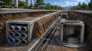
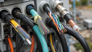
Cable Shields and Armor Metallic shields, armor, and strength members of buried or ducted cable must be effectively grounded and bonded. NESC Part 3 contains specific rules for underground communications cables, including bonding intervals and common grounding in manholes.
Manholes and Handholes All metallic components (racks, covers, cable shields, grounding electrodes) within a manhole or handhole are bonded together and connected to a common ground. Corrosion-resistant conductors and connections are required.
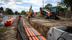
Direct-Buried Plant BICSI G4-23 addresses bonding and grounding of direct-buried facilities, including pole grounds at transitions and bonding within joint-use trenches. Detectable warning tape and tracer wires must not compromise the grounding system.
Random Separation Where communications and power cables share a trench with limited separation, NESC imposes additional bonding requirements (typically at intervals not exceeding 1,000 ft / 300 m) to limit voltage differences during faults.
8.5 Building Entrance and Intersystem Bonding
At the building entrance facility the OSP metallic members are bonded to the telecommunications grounding system (typically the primary bonding busbar) and interconnected with the electrical grounding electrode system. This intersystem bond is critical for equalizing potentials during lightning or power-fault events. Primary protectors on copper pairs are bonded to the same system. NEC and TIA-607 requirements apply on the premises side of the entrance.
8.6 Surge and Lightning Protection
- Primary protectors are required on metallic pairs entering buildings.
- Optical fiber itself requires no surge protection, but any metallic members or hybrid cables do.
- In high-lightning or high ground-potential-rise areas (near substations or power plants), specialized isolation, neutralizing transformers, or enhanced grounding electrode systems may be necessary.
- Coordination with the facility’s lightning protection system (NFPA 780) is recommended for critical government and utility sites.
8.7 Design and Installation Practices
- Use corrosion-resistant conductors and listed connectors suitable for the environment.
- Minimize connection resistance; exothermic welds or listed irreversible compression connectors are preferred for permanent bonds.
- Maintain accessibility for inspection and testing where practical.
- Document all bonding and grounding connections on as-built drawings.
- Test continuity and resistance of the completed system as part of acceptance.
ANSI/BICSI N3-20 provides detailed planning and installation methods that complement the NESC safety rules and are widely referenced for professional ICT work.
8.8 Application Notes by Network Type
Campus — Emphasis on clean intersystem bonding at multiple building entrances and coordination with the overall campus grounding system. Carrier — Strict adherence to NESC multi-grounded system rules and company-specific bonding standards along long routes. Utility — Heightened attention to induction, ground-potential rise, and bonding to the power multi-grounded neutral. Government — Often includes enhanced electrode systems, isolation requirements, and security-related restrictions on accessible grounding points.
8.9 Summary
Bonding, grounding, and electrical protection form a critical safety and reliability layer for all OSP pathways. Design and construction must satisfy the mandatory requirements of the 2023 NESC, incorporate the installation practices of ANSI/BICSI N3-20 and the BICSI G-series standards, and address the specific exposure risks of the route. All-dielectric designs simplify many of these requirements and should be considered where electrically hostile environments exist. Proper execution protects personnel, equipment, and network availability for the life of the plant.