5.1 Purpose and Scope
Direct-buried pathways place telecommunications cable directly in the soil without continuous conduit, relying on the cable construction, burial depth, warning systems, and careful route design for protection. When properly engineered, direct-buried systems offer a cost-effective solution for many campus, carrier, utility, and government routes, particularly in open or lightly developed corridors.
This chapter provides design and construction guidance aligned with BICSI G4-23 (ICT Outside Plant Construction and Installation: Direct Buried Facilities), the Outside Plant Design Reference Manual (OSPDRM) 6th Edition, ANSI/TIA-758-B, IEEE C2-2023 (NESC), and related industry practices. It addresses route planning, placement methods, protection measures, transitions, and environmental considerations.
5.2 When Direct-Buried Construction Is Appropriate
Direct-buried pathways are typically selected when:
- Future cable additions are unlikely or can be accommodated by parallel placement.
- Surface restoration costs or disruption must be minimized after initial construction.
- Soil conditions are favorable and frost depth, rock, or high water tables do not create excessive risk.
- Budget constraints favor lower initial capital cost over maximum future flexibility.
They are generally less suitable for high-growth campus backbones, congested urban corridors, or routes where frequent cable adds or rapid restoration are expected. In those cases, underground duct systems (Chapter 4) are preferred.
5.3 Route Design and Planning
Route selection must consider:
- Existing and planned utilities (strict coordination with one-call systems and utility owners is mandatory).
- Soil type, stability, corrosivity, and drainage.
- Frost depth and potential for frost heave.
- Surface loading (vehicle traffic, agricultural activity, future construction).
- Environmental constraints (wetlands, protected habitats, cultural resources).
- Accessibility for construction equipment and future maintenance.
The design must maintain required separations from other utilities per NESC Rule 352 and local regulations. Vertical and horizontal separations from power facilities require particular attention in utility corridors to manage induction and ground-potential rise risks.
5.4 Burial Depth and Protection
Minimum cover is established by NESC, local codes, and project specifications. Typical values are:
- 24 in (600 mm) in non-traffic areas.
- 36 in (900 mm) or greater under roadways, driveways, and parking areas.
- Deeper burial where frost depth, soil conditions, or AHJ requirements dictate.
Additional protection measures include:
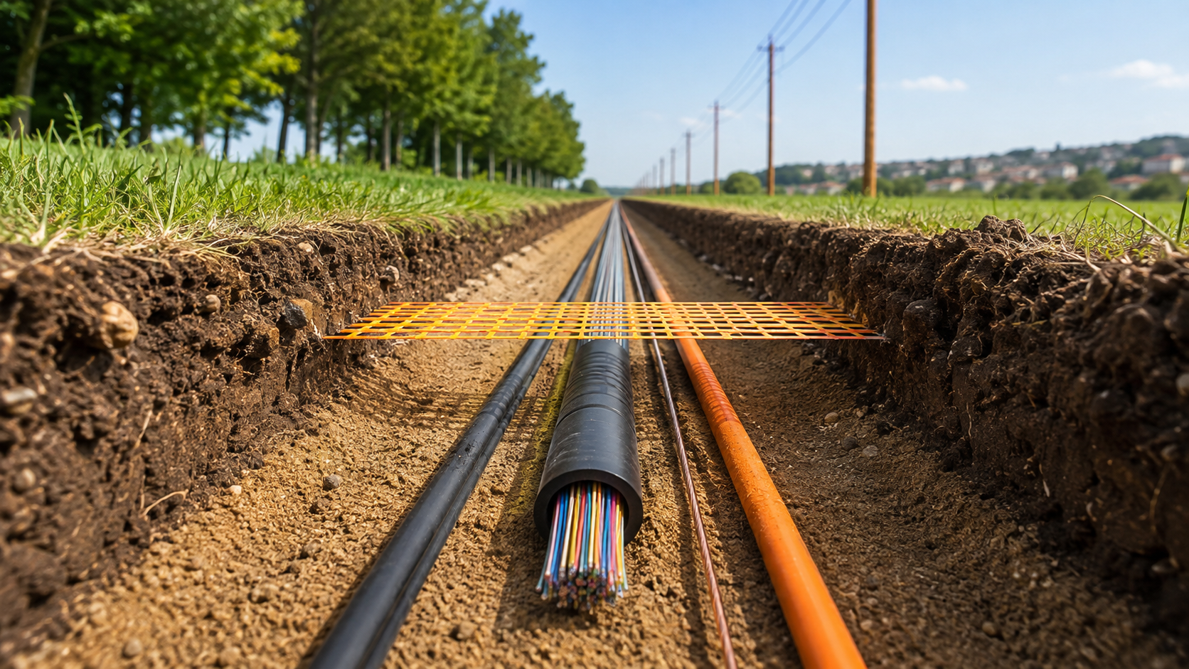
- Warning tape (detectable or non-detectable) placed 12 in (300 mm) above the cable.
- Continuous tracer wire or electronic marker systems for future locating.
- Select backfill free of rocks and debris in the cable zone.
- Concrete or other mechanical protection at crossings or high-risk locations.
- Cable constructions rated for direct burial (armor, double jacket, or equivalent as specified by ICEA and manufacturer data).
5.5 Placement Methods
Common methods include:
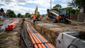
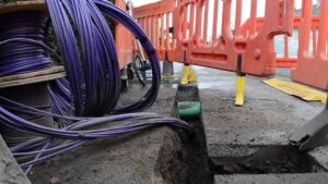
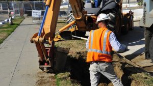
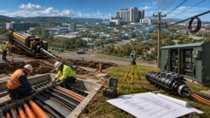
- Open-cut trenching — Most controlled method; allows precise depth, bedding, and placement of warning systems.
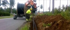
- Plowing — Efficient for long runs in suitable soils; requires careful monitoring of depth and cable tension.
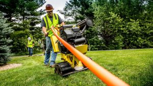
- Direct boring or vibratory methods — Used selectively for shorter segments or sensitive surfaces.
- Hydro-excavation or vacuum methods — Preferred near existing utilities to reduce damage risk.
All methods must comply with OSHA excavation safety rules and maintain cable minimum bend radius and maximum pulling tension limits. Cable must be installed without excessive side-wall pressure or damage to the jacket.
5.6 Transitions and Special Locations
Transitions to underground conduit, aerial plant, or building entrances require detailed design. Typical elements include:
- Short conduit sleeves or continuous conduit sections at road crossings, under paved areas, or at building entrances.
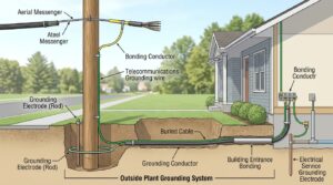
- Riser poles or pedestals for aerial transitions.
- Proper sealing and anchoring at all transition points.
- Maintenance of bonding and grounding continuity.
At building entrances, NEC limitations on unlisted outside-plant cable length and firestopping requirements apply.
5.7 Environmental and Restoration Considerations
Direct-buried construction must address:
- Erosion control and storm-water management during and after construction.
- Restoration of surface grades, vegetation, and pavements to equal or better condition.
- Protection of tree roots and sensitive landscape features on campus and government sites.
- Compliance with environmental permits and any seasonal restrictions.
In corrosive soils or areas with high groundwater, cable selection and possible use of continuous conduit segments become critical.
5.8 Documentation and Quality Assurance
Design documents must show plan view, typical trench details, burial depths, warning system placement, and transition details. Construction quality assurance includes:
- Verification of depth and alignment.
- Confirmation of warning tape and tracer systems.
- Visual inspection of cable during placement.
- Complete as-built records, preferably GIS-compatible, showing final cable location and depth.
Acceptance occurs before the trench is closed whenever practical.
5.9 Application Notes by Network Type
Campus — Often used for lower-priority or spur routes; aesthetic restoration and coordination with landscape plans are important. Carrier — Common for long rural or suburban routes; rapid restoration capability and accurate locating systems are emphasized. Utility — Frequent use alongside other buried utilities; strict separation and induction mitigation required. Government — May be acceptable for non-critical routes; security and long-term locating accuracy remain priorities.
5.10 Summary
Direct-buried facilities can provide reliable, economical OSP pathways when route conditions, growth expectations, and protection measures are properly evaluated. Design in accordance with BICSI G4-23, NESC requirements, and sound engineering judgment produces infrastructure that meets professional standards for campus, carrier, utility, and government applications. Where future flexibility or higher protection is required, underground duct systems should be selected instead.