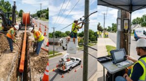
6.1 Purpose and Scope
Aerial pathways remain a widely used and cost-effective method for deploying OSP cabling across campus, carrier, utility, and government networks. When properly designed and constructed, aerial systems provide rapid deployment, relatively low initial cost, and straightforward access for maintenance and restoration. They also introduce unique challenges related to clearances, structural loading, joint-use arrangements, weather exposure, and long-term reliability.
This chapter provides professional guidance for the design and construction of aerial OSP pathways and support structures in accordance with BICSI G2.1-22 (Pole Setting, Anchoring, and Guying), BICSI G2.2-22 (Aerial Cable Installation), the Outside Plant Design Reference Manual (OSPDRM) 6th Edition, IEEE C2-2023 (National Electrical Safety Code), and related industry practices. It addresses poles and support structures, messenger strand, lashed and self-supporting cable (including ADSS), clearances, joint-use/make-ready processes, and transitions.
6.2 Design Objectives
Aerial pathway design must achieve:
- Compliance with NESC strength, loading, and clearance requirements for the applicable loading district and structure class.
- Adequate capacity for initial and future cable attachments.
- Safe working clearances for construction and maintenance personnel.
- Compatibility with existing or planned joint-use arrangements.
- Acceptable reliability given local weather, vegetation, and traffic conditions.
- Proper transitions to underground, direct-buried, or building entrance facilities.
6.3 Support Structures – Poles, Anchors, and Guys
Poles Wood, steel, concrete, or composite poles may be used. Selection depends on required strength, height, expected loading, environmental conditions, and owner preference. Pole class and length must satisfy NESC strength requirements under the governing loading conditions (including extreme wind and ice where applicable). Setting depth, backfill, and alignment follow BICSI G2.1-22 and local practice.
Anchors and Guys Guys and anchors provide the necessary stability against unbalanced loads, especially at corners, dead-ends, and long spans. Anchor types (screw, plate, rock, etc.) are selected according to soil conditions. Guy wires must be properly tensioned, insulated or grounded as required, and protected from vehicle or pedestrian contact. BICSI G2.1-22 provides detailed methods for pole setting, anchoring, and guying.
Attachments and Space Allocation On joint-use poles, communications facilities occupy the designated communications space below the power supply space, with required vertical separations maintained per NESC. The Designer must determine available attachment space, existing attachments, and any make-ready work required before new cable can be placed.
6.4 Cable Support Systems
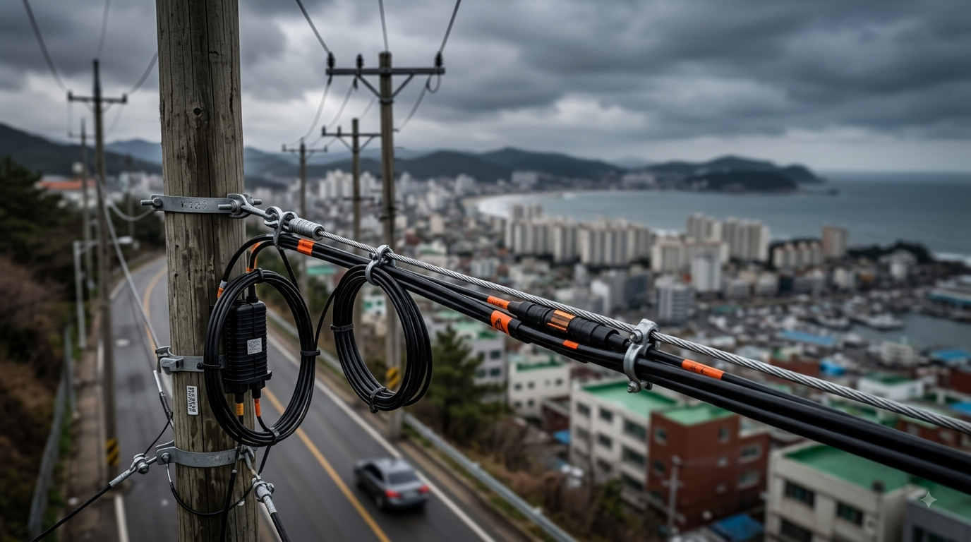
Messenger Strand with Lashed Cable A steel messenger strand is installed first and tensioned to design sag. Telecommunications cable is then lashed to the strand using appropriate lashing wire and methods. This remains the most common aerial construction method for both fiber and copper.
Self-Supporting Cable All-dielectric self-supporting (ADSS) cable and figure-8 designs eliminate the need for a separate messenger in many applications. ADSS is particularly valuable near power lines because it is non-conductive. Span length, sag, and tension must be calculated according to manufacturer data and NESC loading criteria. OSPDRM 6th Edition includes specific guidance on ADSS aerial installation.
Other Methods Over-lashing existing cables, use of existing strand, and specialized bridge or building attachments are evaluated on a case-by-case basis.
6.5 Clearances and Loading
NESC Part 2 governs vertical, horizontal, and radial clearances from ground, roadways, railways, water surfaces, buildings, and other conductors. Clearances must be maintained under maximum sag conditions. The 2023 NESC includes updated provisions for storm loading and certain island/coastal zones that must be applied where relevant.
Structure strength and loading calculations must consider:
- Vertical loads (cable weight, ice)
- Transverse loads (wind)
- Longitudinal loads (unequal spans, broken conductors)
- Combined loading cases required by NESC
Failure to meet clearance or strength requirements is a primary cause of regulatory non-compliance and safety incidents.
6.6 Joint-Use and Make-Ready
In most utility corridors, poles are owned by the electric utility or a joint-use authority. New attachments typically require a formal application, engineering review, make-ready work (pole replacement, guying, rearrangement of existing attachments), and execution of a joint-use or attachment agreement. The OSP Designer must identify ownership early, understand the make-ready process and timelines, and incorporate associated costs and schedule impacts into the project plan. OSPDRM 6th Edition contains updated material on joint-use and make-ready activities.
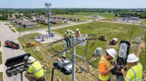
6.7 Placement and Construction Practices
BICSI G2.2-22 details methods for installing support strand, placing and lashing cable, and installing self-supporting cable. Key controls include:
- Proper tensioning and sag
- Protection of cable during pulling and lashing
- Maintenance of minimum bend radius
- Correct placement of splice closures and slack storage
- Bonding and grounding of metallic members
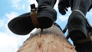
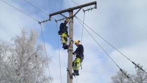
Construction must follow OSHA safety rules for aerial work, including fall protection and traffic control.
6.8 Transitions
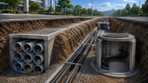
Aerial-to-underground or aerial-to-direct-buried transitions require riser poles or dedicated transition structures with appropriate conduit, cable protection, and grounding. Building attachments must satisfy both NESC and NEC requirements at the point of entrance.
6.9 Application Notes by Network Type
Campus — Aerial construction is often restricted by aesthetics or institutional policy; where permitted, it is typically limited to secondary routes or temporary needs. Carrier — Widely used for long-haul and access routes; ADSS and high-count fiber are common. Joint-use processes are routine. Utility — Frequent joint-use with power; strict NESC separation and induction considerations apply. Government — May be acceptable for non-critical routes; security, reliability, and long-term maintenance access remain priorities.
6.10 Documentation and Quality Assurance
Design documents must include plan views, pole schedules, loading and clearance calculations, typical attachment details, and references to governing NESC rules and BICSI standards. As-built records should capture final pole locations, attachment heights, cable counts, and any deviations from design.
6.11 Summary
Aerial pathways offer practical advantages when clearances, structural capacity, joint-use constraints, and environmental exposure are properly addressed. Design and construction in accordance with BICSI G2.1-22, G2.2-22, the OSPDRM 6th Edition, and the 2023 NESC produce safe, reliable aerial infrastructure suitable for campus, carrier, utility, and government applications. Ongoing BICSI work on a new general aerial pathways standard (D051) should be monitored for future updates.
FAQ
What is an aerial OSP pathway?
An aerial OSP pathway is an above-ground telecommunications route used to support fiber optic, copper, and other communications cables on poles or dedicated support structures.
What standards govern aerial OSP cable installation?
Aerial OSP design commonly incorporates applicable requirements and guidance from the NESC, BICSI standards, the OSPDRM, utility attachment rules, and applicable electrical and occupational safety requirements.
What is ADSS cable?
ADSS, or All-Dielectric Self-Supporting cable, is a fiber optic cable designed to span between support structures without requiring a metallic messenger. Its non-conductive construction makes it useful in environments where electrical considerations are important.
What is make-ready work?
Make-ready work consists of modifications required to a pole or existing attachments before a new communications cable can be safely installed. Work may include pole replacement, guying, rearrangement of existing facilities, and other structural or clearance modifications.
Why are aerial cable clearances important?
Required clearances protect the public, workers, vehicles, buildings, electrical facilities, and telecommunications infrastructure. Designers must account for conditions such as maximum sag, wind, ice, and other applicable loading scenarios.
What factors determine aerial pole selection?
Pole selection depends on required height, strength, span length, cable loading, wind and ice conditions, existing attachments, soil conditions, environmental exposure, and applicable structural requirements.
What information should be included in aerial OSP design documents?
Typical documentation includes plan views, pole schedules, attachment heights, loading and clearance calculations, construction details, cable information, guy and anchor requirements, splice locations, and applicable standards and regulations.