Edition 2026 | For BICSI RCDD, OSP Designers, ICT Consultants, and Network Engineers
CHAPTER 1 — INTRODUCTION TO OUTSIDE PLANT (OSP)
1.1 Purpose
Outside Plant (OSP) engineering is the discipline responsible for the physical telecommunications infrastructure that exists beyond the building entrance facility — the conduits, duct banks, aerial cable, fiber, copper, and support structures that carry voice, data, video, and control signals between buildings, campuses, cities, and continents. Where inside plant (ISP) design addresses cabling within a single structure, OSP design contends with civil works, right-of-way negotiation, environmental exposure, utility coordination, and decades-long service life expectations. It is, in practical terms, the engineering of the physical layer that everything else in modern telecommunications depends on.
An OSP network typically originates at a building entrance facility (BEF) or network interface, and extends outward through underground, aerial, or direct-buried pathways to remote buildings, equipment cabinets, wireless transmission sites, or a carrier’s point of presence. Every enterprise campus, hospital network, government facility, utility SCADA system, and metropolitan carrier network depends on OSP infrastructure engineered to remain reliable for twenty, thirty, or more years under continuous environmental and mechanical stress.
The primary objectives that govern OSP engineering practice are:
Ensure reliable, uninterrupted communications across the service life of the asset
Provide scalable infrastructure that accommodates growth without full reconstruction
Support future technology migration (e.g., copper-to-fiber, PON overlays, 5G backhaul)
Minimize total lifecycle cost, not just initial construction cost
Improve long-term maintainability through documentation and spare capacity
Ensure resilience against environmental hazards — flooding, seismic activity, extreme temperature, and physical damage
Meet all applicable safety, performance, and regulatory standards
A well-engineered OSP network is invisible when it works and catastrophic when it fails. This duality is what makes OSP engineering a discipline of consequence: a single duct bank routed through the wrong soil conditions, or a splice closure installed without proper strain relief, can produce an outage that surfaces years after construction is complete and the design engineer has moved to another project.
1.1.1 The OSP/ISP Boundary in Practice
The line between OSP and ISP is not always the building wall itself, and misidentifying it is a recurring source of scope disputes between design teams and contractors. The building entrance facility (BEF) — the point where outside cable transitions to inside cable, typically via a splice, patch panel, or protector block — is the conventional demarcation point defined in ANSI/TIA-758-B. Everything on the outside-facing side of that demarcation, including the entrance conduit stub-up, the outdoor-rated portion of the cable run within the building (per NEC Article 800 listing requirements), and any grounding conductor bonded to the building’s electrical service, is properly considered OSP scope even though it may be physically located within the building envelope. RCDDs should treat the BEF, not the exterior wall, as the true scope boundary when writing specifications and coordinating between OSP and ISP design teams.
1.2 Definition of Outside Plant
Outside Plant includes all passive telecommunications infrastructure located beyond the building entrance facility. This includes, but is not limited to:
Underground conduit systems and innerduct
Duct banks (single and multi-duct, concrete-encased or direct-buried)
Handholes and pull boxes
Manholes and vaults
Direct-buried cable (armored and unarmored)
Aerial cable, messenger strand, and lashing systems
Pole lines and joint-use attachments
Fiber optic cable in all configurations (loose-tube, ribbon, armored, ADSS, figure-8, microduct/blown fiber)
Copper cable (twisted-pair, pressurized, hybrid)
Cabinets, pedestals, and below-grade enclosures
Splice closures and distribution terminals
Distribution hubs and fiber distribution panels
Wireless support infrastructure (monopoles, DAS nodes, small-cell mounts)
Grounding, bonding, and lightning-protection systems
The distinguishing characteristic of OSP, as opposed to ISP, is exposure: OSP infrastructure is subject to soil chemistry, groundwater, freeze-thaw cycling, UV degradation, wind and ice loading, third-party excavation damage, rodent and insect intrusion, and vehicular impact. Every material selection and design decision in OSP engineering is made in the context of this exposure, and standards bodies such as BICSI, TIA, and the NESC reflect that reality in their construction and testing requirements.
1.3 Scope of OSP Engineering
OSP engineering is inherently multidisciplinary. A design that satisfies telecommunications performance requirements but ignores civil, electrical, geotechnical, or environmental constraints will fail in construction, in service, or in permitting. The RCDD or OSP designer functions as an integrator across these disciplines rather than a specialist confined to any one of them.
Telecommunications engineering governs network architecture, capacity planning, fiber topology, and cable routing — the logical design that the physical infrastructure must support.
Civil engineering governs excavation methods, road and rail crossings, drainage design, and structural foundations for cabinets, vaults, and pole structures. OSP routes frequently run parallel to or cross roadways, requiring coordination with municipal and state departments of transportation.
Electrical engineering governs bonding, grounding, lightning protection, and — where applicable — power distribution to remote electronics such as amplifiers, wireless nodes, or PON remote terminals. Improper bonding and grounding is among the most common root causes of OSP-related equipment failure and personnel safety incidents.
Geotechnical engineering governs soil classification, rock conditions, groundwater table depth, and slope stability — all of which directly affect trenching method, conduit material selection, and handhole/vault design.
Environmental engineering governs wetland delineation, protected habitat avoidance, erosion and sediment control, and stormwater management, particularly on projects subject to NEPA, state environmental review, or local wetland ordinances.
Project management governs scheduling, cost estimation, procurement strategy, and construction oversight — disciplines covered in depth in Part IV of this handbook.
A design team that treats these as sequential, siloed inputs rather than as concurrent constraints will produce designs that require costly rework during permitting or construction. Effective OSP engineering integrates civil, electrical, geotechnical, and environmental input from the feasibility stage forward, not as an afterthought to the telecommunications design.
1.4 Types of OSP Networks
Campus Networks
Campus networks serve multiple buildings under common administrative control — universities, hospital systems, corporate campuses, and industrial or government facilities. These networks typically feature redundant fiber rings between a main distribution frame and building entrance facilities, centralized network administration, and high-capacity backbone links sized for both current utilization and a defined growth horizon (commonly 15–20 years for the outside plant cable itself, even where electronics are refreshed every 3–7 years). Campus OSP design frequently must account for underground utility congestion in older, densely built environments, as well as accommodate future building additions without requiring re-trenching of primary pathways.
Metropolitan Area Networks (MANs)
MANs connect facilities across a city or region — linking enterprise campuses, government offices, hospitals, schools, data centers, and carrier points of presence. MANs commonly use ring or mesh topologies specifically to provide route diversity and protection switching in the event of a single fiber cut, which is a materially higher risk in a metropolitan environment with continuous third-party excavation activity. Route diversity in MAN design is not merely a topology preference; it is frequently a contractual or regulatory requirement for carrier-grade or public-safety networks.
Long-Haul Networks
Long-haul networks span hundreds to thousands of kilometers, interconnecting cities, countries, and international gateways. These networks require optical amplification and regeneration at defined intervals, aggressive route diversity across independent physical corridors, and design hardening against environmental hazards ranging from seismic activity to marine cable hazards for submarine segments. Long-haul OSP design also carries the highest consequence-of-failure profile in the industry: a single cable cut on an under-provisioned long-haul route can isolate regional traffic for hours before restoration.
Utility Networks
Utility OSP networks support electric transmission and distribution, water and wastewater SCADA, gas pipeline monitoring, transportation control systems, and public-safety communications. These networks frequently combine fiber (including OPGW — optical ground wire — on transmission structures), microwave, and licensed wireless technologies, and are typically engineered to reliability targets substantially higher than commercial enterprise networks given their role in life-safety and critical-infrastructure operations. Utility networks are also subject to a distinct regulatory regime — NERC CIP requirements for the electric sector, for example — that layers additional physical-security design requirements onto standard OSP practice.
1.5 OSP Infrastructure Components
Underground Systems
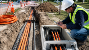
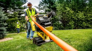
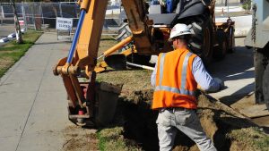
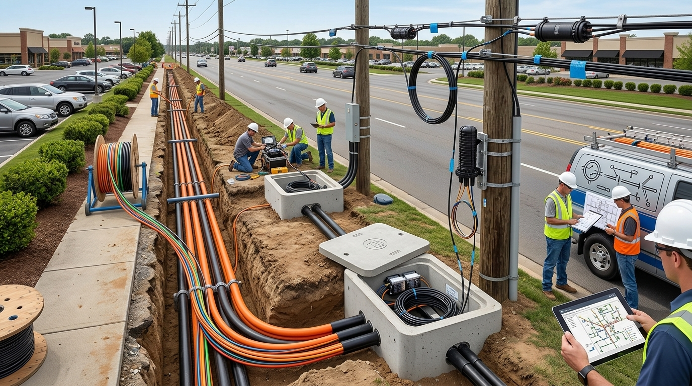
Underground OSP construction includes conduit and innerduct, concrete-encased or direct-buried duct banks, manholes, handholes, pull boxes, vaults, and surface marker posts or ball markers for locate purposes. Underground construction offers the highest protection from environmental and physical damage but carries the highest first cost and the longest restoration time in the event of damage or expansion, since access requires excavation.
Aerial Systems
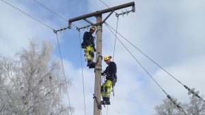
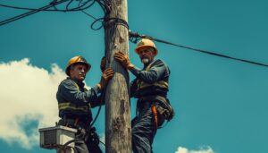
Aerial OSP construction includes utility poles (owned or joint-use), messenger strand, lashing wire, pole-line hardware, guy wires, and anchors. Aerial construction offers lower first cost and faster restoration than underground systems but carries materially higher exposure to wind, ice, vehicular strikes, and vegetation contact — factors that must be explicitly modeled in structural loading calculations under NESC.
Fiber Infrastructure
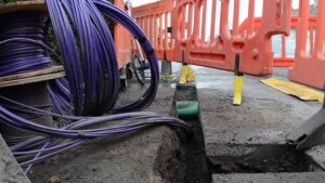
Fiber cable constructions used in OSP applications include loose-tube cable (the dominant OSP construction for its water-blocking and crush-resistance characteristics), ribbon cable (favored for very-high-fiber-count applications due to mass-fusion splicing efficiency), armored cable (for rodent-prone or direct-buried applications), All-Dielectric Self-Supporting (ADSS) cable (for aerial spans without a messenger strand), figure-8 cable (integrated messenger for aerial runs), and microduct/blown-fiber systems (which allow fiber to be installed or upgraded within pre-placed microduct without disturbing the pathway).
Copper Infrastructure
Although fiber has displaced copper as the dominant OSP medium for new construction, twisted-pair copper, air-core pressurized cable, and hybrid fiber/copper systems remain in service across legacy campus and utility networks, and OSP designers must be conversant in copper splicing, pressurization, and testing practices to support, maintain, or plan the migration of these legacy systems.
Wireless and Small-Cell Support Infrastructure
As campus and metropolitan networks increasingly carry wireless backhaul, monopoles, DAS (distributed antenna system) nodes, and small-cell mounts have become a standard OSP scope item rather than a separate wireless-only discipline. These structures require the same foundation, grounding, and structural-loading analysis as any other pole or tower asset, and the fiber and power feeds to them are engineered using conventional OSP methods — underground or aerial cable runs terminating at a base-mounted cabinet. OSP designers working on smart-city or 5G-densification projects should expect small-cell siting to be governed by both telecommunications standards and local zoning/aesthetic ordinances, which frequently impose pole height, color, and concealment requirements beyond what is required for a conventional utility pole.
1.6 Stakeholders
An OSP project routinely involves stakeholders whose interests and constraints do not naturally align, and part of the OSP designer’s function is to reconcile these competing requirements into a single constructible design. Typical stakeholders include:
Telecommunications carriers and internet service providers, whose network requirements and existing facilities constrain routing options
Enterprise network owners, whose operational and budget requirements drive project scope
Utility companies (electric, gas, water), whose existing underground and aerial facilities must be identified and avoided or coordinated with
Government agencies, both as project owners and as permitting authorities
Civil engineering consultants and surveyors, who provide the site data the OSP design depends on
ICT consultants and RCDDs, who translate business requirements into technical design
Contractors, who must be able to constructibly execute the design within the available right-of-way
Regulatory authorities, including state utility commissions, departments of transportation, and environmental agencies
Property owners, whose easement grants or denials directly determine route feasibility
1.7 Network Design Objectives
Every OSP design decision should be evaluated against six core objectives:
Reliability — continuous operation with minimal unplanned outages, achieved through route diversity, protected splice enclosures, and construction methods appropriate to the exposure environment.
Availability — a quantified uptime objective, commonly expressed in “nines.” Carrier-grade and public-safety networks frequently target 99.999% availability (approximately 5.26 minutes of unplanned downtime per year), which is achievable only through redundant physical paths and diverse entrance facilities, since no single-path OSP design can meet that target regardless of cable quality.
Scalability — the ability to accommodate future capacity growth without requiring reconstruction of primary pathways, typically achieved by sizing conduit, duct bank, and vault capacity to a 15–20 year growth horizon even where initial fiber counts are modest.
Maintainability — accessible infrastructure, complete and current as-built documentation, and spare fiber/duct capacity, all of which materially reduce mean time to repair (MTTR) when a fault occurs.
Security — protection against physical intrusion, vandalism, and accidental third-party damage, addressed through enclosure hardening, locking hardware, and — for critical infrastructure — compliance with sector-specific physical security regulations.
Sustainability — consideration of energy use in active electronics, environmental impact of construction methods, and long-term asset management practices that avoid premature replacement of usable infrastructure.
| Availability Target | Approx. Annual Downtime | Typical Application |
|---|---|---|
| 99.9% | ~8.76 hours | Standard enterprise campus |
| 99.99% | ~52.6 minutes | Carrier MAN, hospital network |
| 99.999% | ~5.26 minutes | Carrier-grade core, public safety |
| 99.9999% | ~31.5 seconds | National long-haul core, financial exchanges |
1.8 Typical OSP Project Lifecycle
An OSP project proceeds through a defined sequence of phases, each of which produces deliverables that constrain the phases that follow. Skipping or compressing an early phase — most commonly the site survey or utility investigation — is the single most common source of cost overrun and schedule delay in OSP construction.
| Phase | Key Activity |
|---|---|
| 1. Needs assessment | Define bandwidth, redundancy, and service requirements |
| 2. Preliminary design | Establish conceptual routing and technology approach |
| 3. Feasibility study | Confirm technical, regulatory, and budgetary viability |
| 4. Survey | Field-verify existing conditions, topography, and access |
| 5. Utility investigation | Locate and document existing underground/aerial utilities |
| 6. Route selection | Select final route based on survey and utility data |
| 7. Detailed engineering | Produce construction-ready drawings and specifications |
| 8. Cost estimating | Develop construction cost estimate for budgeting/bidding |
| 9. Permitting | Obtain right-of-way, environmental, and construction permits |
| 10. Procurement | Bid and award construction and material contracts |
| 11. Construction | Execute civil and cable placement work |
| 12. Inspection | Verify construction complies with design and code |
| 13. Testing | Perform OTDR, insertion loss, and continuity testing |
| 14. Commissioning | Activate and verify end-to-end service performance |
| 15. As-built documentation | Update design records to reflect actual construction |
| 16. Operations and maintenance | Ongoing inspection, repair, and capacity management |
1.9 Standards and Regulatory Context
OSP design does not occur in a regulatory vacuum. The standards landscape covered in depth in Part III of this handbook governs nearly every material and construction decision at the OSP level: ANSI/TIA-758-B establishes customer-owned outside plant telecommunications infrastructure standards; the BICSI OSP Design Reference Manual provides the industry’s primary design methodology reference; the National Electrical Safety Code (NESC) governs clearance, loading, and grounding requirements for aerial and underground electric-adjacent construction; and the National Electrical Code (NEC) governs bonding and grounding at building entrance facilities. State and municipal right-of-way ordinances, One-Call/utility-locate statutes, and — where wetlands, floodplains, or protected species are present — federal environmental review requirements layer additional constraints onto the design. An RCDD or OSP designer is expected to know not only which standard governs a given design decision, but how those standards interact when a project crosses multiple jurisdictions.
1.9.1 Working Across Jurisdictional Boundaries
Many OSP projects — particularly MAN and long-haul routes — cross multiple permitting jurisdictions within a single design, and each jurisdiction may apply its own right-of-way, One-Call/utility-locate, and construction-method requirements on top of the national standards discussed above. A route that transitions from a state highway right-of-way to a municipal street to a private easement can trigger three distinct permitting processes, three distinct utility-locate requirements, and, in some cases, three distinct construction-method restrictions (for example, a municipality may prohibit open-cut trenching on a recently resurfaced street, forcing a directional-bore method for that segment only). Experienced OSP designers build jurisdictional research into the feasibility phase specifically so that these constraints are identified before detailed engineering begins, rather than discovered during permitting, when a design change can consume weeks of schedule float.
1.10 Chapter Summary
Outside Plant engineering is the physical foundation on which every higher-layer network service depends, and it is inherently multidisciplinary — spanning telecommunications, civil, electrical, geotechnical, and environmental engineering under a single project scope. The four principal network types (campus, MAN, long-haul, and utility) share common infrastructure components but differ substantially in redundancy requirements, consequence of failure, and regulatory context. Every design decision should be evaluated against the six core objectives of reliability, availability, scalability, maintainability, security, and sustainability, and every project proceeds through a defined sixteen-phase lifecycle in which early-phase rigor — particularly survey and utility investigation — determines downstream cost and schedule performance. The chapters that follow build progressively on this foundation, beginning with the historical evolution of the infrastructure introduced here.
Looking Ahead
This handbook is organized so that each subsequent chapter builds directly on the vocabulary and framework established here. Chapter 2 traces the evolution of telecommunications infrastructure from early copper-based systems through the fiber and PON deployments that dominate current construction, giving context for why legacy copper plant still matters to a designer working primarily in fiber. Chapter 3 develops the network architectures and topologies referenced only briefly in Section 1.4, with worked examples of ring, mesh, and star configurations and the fiber-count and route-diversity calculations that support each. Readers who are new to OSP design should treat this chapter’s definitions and objectives as the shared vocabulary the remainder of Volume 1 assumes.
Review Questions
1. What distinguishes Outside Plant (OSP) from Inside Plant (ISP), and why does that distinction drive different material and design requirements?
2. Name the five engineering disciplines that intersect in OSP design and give one example decision governed by each.
3. Compare the redundancy and route-diversity requirements of a campus network versus a long-haul network. Why do they differ?
4. What does a 99.999% availability target mean in terms of annual downtime, and what design characteristic is required to achieve it?
5. List the sixteen phases of the OSP project lifecycle and identify the two phases most commonly compressed or skipped — and the consequence of doing so.
6. Which standards govern aerial clearance and loading requirements for OSP construction adjacent to electric facilities?
7. Why is grounding and bonding design frequently cited as a root cause of OSP-related equipment failure?
8. Identify three stakeholder groups whose interests in an OSP project are most likely to conflict, and explain why.