- Fiber selection is application-specific, not universal: G.652.D remains the standard for long-haul and feeder/distribution OSP runs, while G.657.A1/A2 is purpose-built for tight-radius FTTx drops and handhole congestion, tolerating bend radii as small as 7.5 mm with minimal macrobend loss.
- Dry water-blocking has displaced gel-filled loose-tube designs in most new OSP builds, using superabsorbent polymer (SAP) yarns and tapes to cut splice prep time and reduce cable weight.
- Armoring choice depends on the threat, not just the budget: corrugated steel tape (CST) protects against rodents and shovel strikes, but dielectric armor (FRP or aramid yarn) is required near high-voltage pathways or in high-lightning zones to avoid grounding obligations.
- 1625 nm OTDR testing is the QA differentiator: macrobends that hide at 1310 nm become clearly visible at 1625 nm, making it the wavelength auditors rely on to catch installation defects before they become service-affecting.
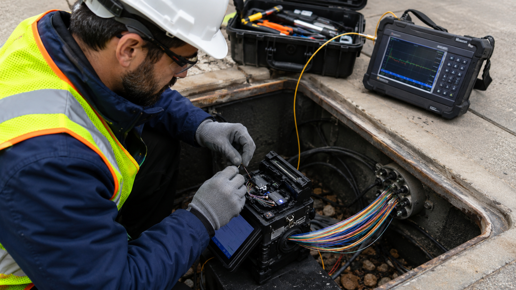
- Splice loss and slack management are non-negotiable tolerances: fusion splices must stay at or below 0.05 dB, with 30 meters of slack held at handholes and 1.5–3 meters buffered at splice closures for future rework.
Why Fiber Selection Still Splits Along Application Lines
Outside plant (OSP) cabling is asked to do something indoor fiber never has to: survive decades of freeze-thaw cycling, soil movement, moisture intrusion, and mechanical abuse, without a controlled environment to fall back on. That reality is why the industry has never converged on a single fiber type for every OSP scenario — the physics of bend tolerance and the economics of long-haul attenuation pull in different directions.
G.652.D, the standard single-mode fiber, remains the default for feeder, distribution, and long-haul OSP links. It’s a known quantity with decades of deployment history, but it comes with a real mechanical constraint: a minimum bend radius of 30 mm, and up to 0.5 dB of macrobending loss at 1625 nm when pushed to that limit.
G.657.A1 and A2, the bend-insensitive variants, exist specifically to solve the problem G.652.D can’t: tight handholes, cramped pedestals, and the indoor/outdoor transitions common in FTTx last-mile drops. G.657.A1 tolerates a 10 mm bend radius; G.657.A2 pushes that down to 7.5 mm while capping macrobend loss at just 0.1 dB. For crews working in congested handholes where cable management space is measured in inches, that difference determines whether a splice closure can be built to spec at all.
Water-Blocking and Armoring: The Mechanical Layer
Two protective decisions shape how well an OSP cable survives its environment over the following decade, and both have moved away from older defaults.
Gel-filled loose-tube designs — the traditional water-blocking method — have largely given way to dry water-blocking technology, built around superabsorbent polymer (SAP) yarns and tapes. The shift isn’t cosmetic: dry designs speed up splice prep by eliminating gel cleanup, and they reduce overall cable weight, which matters on long aerial or duct runs.
Armoring decisions follow a similar “match the threat” logic. Corrugated steel tape (CST) is the standard mechanical protection against rodent chewing and the ever-present risk of shovel strikes during unrelated excavation work. But CST is conductive, which becomes a liability near high-voltage infrastructure or in lightning-prone regions, where induced current and grounding requirements complicate installation. In those cases, dielectric armor — fiberglass-reinforced plastic (FRP) or aramid yarns — removes the conductivity problem entirely, eliminating the need for bonding and grounding hardware along the route.
Testing and Splicing: Where Field Discipline Meets the Spec Sheet
Standards on paper only matter if field practices catch deviations before a network goes live, and this is where OSP QA gets specific.
Every OSP span requires bidirectional OTDR testing at three wavelengths: 1310 nm, 1550 nm, and 1625 nm. The 1625 nm test isn’t redundant — it’s the one that exposes what the other two miss. Macrobends caused by a tight kink or a pinched fiber during installation can be nearly invisible at 1310 nm but show up clearly at 1625 nm, which is exactly why QA audits lean on that wavelength to catch defects that would otherwise surface later as intermittent signal loss.
Splice quality is held to a tight numeric standard: fusion splices on single-mode fiber must not exceed 0.05 dB of loss. That threshold leaves little room for technician error, and it’s a major reason fusion splicing has displaced mechanical splicing almost everywhere loss budgets are tight.
Slack management rounds out the field discipline. Crews are expected to store at least 30 meters (100 feet) of cable slack in OSP handholes, plus 1.5 to 3 meters (5 to 10 feet) of buffered fiber slack within splice closures. That slack isn’t just a convenience — it’s what allows future re-splicing, fault isolation, or route rework without pulling new cable.
FAQ
What’s the practical difference between G.652.D and G.657.A2 fiber? G.652.D is optimized for long, straight OSP runs with a 30 mm minimum bend radius, while G.657.A2 is designed for tight, congested installations, tolerating a 7.5 mm bend radius with far lower macrobend loss.
Why test OTDR at 1625 nm instead of just 1310 or 1550 nm? Macrobends from kinks or pinches are far more visible at 1625 nm, making it the wavelength most likely to catch installation defects that 1310 nm testing would miss.
Why has dry water-blocking replaced gel-filled loose-tube cable? SAP-based dry designs cut splice preparation time and reduce cable weight compared to gel-filled tubes, without sacrificing moisture protection.
When is dielectric armor required instead of corrugated steel tape? Dielectric armor (FRP or aramid yarn) is used near high-voltage pathways or in high-lightning areas, since it’s non-conductive and removes the need for grounding hardware that CST would require.
What’s the maximum allowable loss for a single fusion splice? 0.05 dB per splice is the accepted maximum for single-mode fusion splices in OSP installations.
Closing Analysis
None of these standards are new science — they’re the accumulated result of decades of field failures being traced back to bend radius, water intrusion, or sloppy splice work. What’s shifted is the margin for error: as FTTx densification pushes fiber into tighter handholes and more congested rights-of-way, the gap between G.652.D’s mechanical tolerances and G.657.A2’s is no longer a spec-sheet footnote — it’s the difference between a splice closure that meets code and one that doesn’t. Expect continued pressure toward bend-insensitive fiber in last-mile builds, and toward dielectric armor as more OSP routes share corridors with utility infrastructure.