
Increasing subscriber needs for optical bandwidth will trigger the deployment of optical fibre closer to the subscriber.
Europacable member companies believe that fibre optical cable technology will be most suited to ensure the deployment of “future proof grids”.
The extent to which optical fibre cable are deployed instead of legacy copper pair cables or coaxial cables depends on many variables.
Not only does each physical environment constitute different subscriber dwelling densities (per sqkm), but country conditions must also be taken into account.
The nature of the site will be a key factor in deciding the most appropriate network design and will therefore also trigger the choice of cable design.
The main influences on the method of infrastructure deployment are:
- type of site;
- size of the network;
- initial cost of the infrastructure deployment (CAPEX);
- running costs for the network operation and maintenance (OPEX);
- network architecture, for example PON or Active Ethernet;
- local conditions, for example, local labour costs, local authority restrictions (traffic control), right of ways.
The choice for cable deployment method and technology will determine CAPEX and OPEX, as well as the reliability of the network.
These costs can be optimized by choosing the most appropriate active solution combined with the most appropriate infrastructure deployment methodology.
These cable installation methods include:
- conventional underground duct and cable;
- blown micro-ducts and cable;
- direct buried cable;
- aerial cable;
- other “right of way” solutions.
Key functional requirements for a high bandwidth access network include:
- provision of high-bandwidth services and content to each subscriber;
- a flexible network architecture design with capacity to meet future needs;
- an ultimate direct fibre connection of each end subscriber directly to the active equipment, ensuring maximum available capacity for future service demands;
- support for future network upgrades and expansion;
- minimal disruption during network deployment.
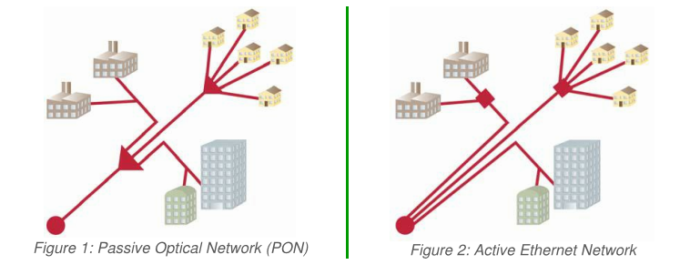
In order to specify the interworking of passive and active infrastructures, it is important to make a clear distinction between the topologies used for the deployment of the fibres (the passive infrastructure) and the technologies used to transport data over the fibres (the active equipment).
The two most widely used topologies are point-to-multipoint, which is often combined with a passive optical network (PON) technology, and point-to-point, which typically uses Ethernet transmission technologies.
Various access network architectures can be implemented:
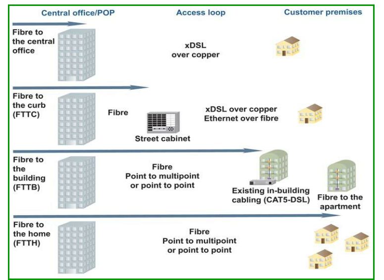
Fibre to the home (FTTH): Each subscriber is connected by a dedicated fibre to a port on the equipment in the POP, or to the passive optical splitter, using shared feeder fibre to the POP and 100BASE-BX10 or 1000BASE-BX10 transmission for Ethernet connectivity or GPON (EPON) in case of point-to-multipoint connectivity.
Fibre to the building (FTTB): Each optical termination box in the building (often located in the basement) is connected by a dedicated fibre to a port in the equipment in the POP, or to an optical splitter which uses shared feeder fibre to the POP.
The connections between subscribers and the building switch are not fibre but can be copper based and involve some form of Ethernet transport suited to the medium available in the vertical cabling.
In some cases building switches are not individually connected to the POP but are interconnected in a chain or ring structure in order to utilize existing fibres deployed in particular topologies.
This also saves fibres and ports in the POP. The concept of routing fibre directly into the home from the POP or through the use of optical splitters, without involving switches in the building, brings us back to the FTTH scenario.
Fibre to the curb (FTTC): Each switch / or DSL access multiplexer (DSLAM), often found in a street cabinet, is connected to the POP via a single fibre or a pair of fibres, carrying the aggregated traffic of the neighbourhood via Gigabit Ethernet or 10 Gigabit Ethernet connection.
The switches in the street cabinet are not fibre but can be copper based using 100BASE-BX10, 1000BASE-BX10 or VDSL2. This architecture is sometimes called “Active Ethernet” as it requires active network elements in the field.
FTTH/B access networks are considered the ultimate target architecture due to their virtually unlimited scalability. When designing and building access networks, it is helpful to understand the challenges and trade-offs facing potential network owners and operators.
Some challenges may result in conflicts between functionality and economic demands. It is quite common that network operators choose for a tiered network upgrade by first deploying FTTC and in a second stage FTTH/B.
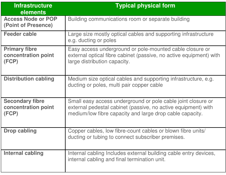
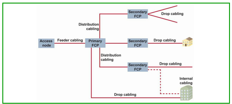
Expanding outwards from the Access Node towards the subscriber, the key infrastructure elements are:
Installation in ducts
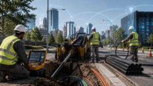
Installing telecommunication cables in ducts is the most conventional method of underground cable installation. It involves creating a duct network to enable subsequent installation of cables using a pulling, blowing or floatation technique.
A conventional duct infrastructure can be constructed in several ways:
- main duct system containing smaller, rigid flexible ducts for individual cable installations;
- large diameter ducts allowing cable to be pulled progressively as the network grows;
- small diameter ducts for single cable installation.
Multiple cables can be installed in a single duct, but need to be put in place simultaneously or alternatively, multiple draw ropes need to be pre-installed. However, a single duct system can limit the number of cables that can be installed.
Entanglement of the cables and high friction between cable jackets may make it difficult to extract older cables from full ducts to allow space for new cable. It is normal for older cables to be located at the bottom of the duct.
Rigid sub ducts reduce the total number of cables that can be installed but also involve the need to remove the older cables. This method incorporates both cable blowing as well as cable pulling, as it helps to create an airtight connection to the sub duct.
Flexible textile sub ducts maximize the total number of cables which can be installed in a duct and at the same time allow older cables to be removed easily. In general, flexible sub ducts triples the number of cables which can be installed in a main duct. Introduction To Telecommunications Cable


