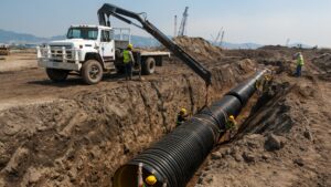
The installation procedure discussed in this section consists of trench floor preparation, providing a sufficiently stable working platform, and meeting the design grade requirements. Following pipe placement, backfill material which has been selected with regards to potential material migration, required density, depth of cover, weight of soil and surcharge loads is installed as follows:
- Bedding material is placed and leveled.
- Haunching is placed and, if required, compacted so as not to disturb the pipe from its line and grade.
- The remainder of the primary initial backfill is placed and, if required, compacted in lifts.
- Secondary backfill is used to protect the pipe during the final backfilling operation and also to provide support for the top portion of the pipe.
- The final backfill may consist of any qualifying material that satisfies road construction or other requirements and, when required, must be compacted.
Trench Floor Preparation
The trench floor must have sufficient stability and load-bearing capacity to present a firm working platform during construction to maintain the pipe at its required alignment and grade and sustain the weight of the fill materials placed around and over the pipe.
The trench bottom should be smooth and free from sloughed sidewall material, large stones, large dirt clods, frozen material, hard or soft spots due to rocks or low-bearing-strength soils, and any other condition that could lead to non-uniform or unstable support of the pipe.
The trench bottom must be kept dry during installation of the pipe and the embedment materials. All foundation and bedding materials must be placed and compacted according to the design
requirements. Such materials should be selected to provide the necessary migration control when required.
Over-excavation of the trench floor by more than 6 inches beyond grade requires that the over-excavation be filled with acceptable embedment material that is compacted to a density equal to that of the embedment material.
If the over excavation exceeds 12 inches, it should be brought to proper grade with a suitably graded Class I or II material that is compacted to the same density as that of the native soil but not less than the density requirements for the embedment materials.
In stable soils the trench floor should be undercut by machine and then brought up to proper grade by use of a well-leveled bedding consisting of a 4 to 6-inch layer of embedment material. This material should be compacted by mechanical means to at least 90 percent Standard Proctor Density. Class I material may be shovel sliced where the depth of cover permits.
In unstable soils that may be too soft, of low load-bearing capacity or otherwise inadequate, the trench bottom must first be stabilized by soil modification, by providing an alternate foundation, or by the removal of the undesirable material and replacement with stable foundation material.
A cushion of at least 4 inches of compacted bedding should be provided between any special foundation and the pipe. Adequacy of trench bottom stability is difficult to evaluate by visual observation and is therefore best determined by soil tests or at the site during installation. However, a warning of a potentially unstable soil condition is given by a trench bottom that cannot support the weight of workmen.
Uneven soil support conditions, where the grade line traverses both soft and hard spots, requires special consideration. Ballasting is the most frequently employed technique to deal with randomly encountered short sections of soft soils.
When differential conditions of pipe support might occur, such as in transitions from manholes to trench or from hard to soft soils, a transition support region should be provided to ensure uniform pipe support and preclude the development of shear, or other concentrated loading on the pipe.
The following procedure may be used:
The soil next to the more rigid support is over-excavated to a depth of not less than 12 inches over a distance of 2 pipe diameters along the pipe line; over the next 2 diameters away from the rigid support, the depth of over-excavation is gradually decreased until it meets the normal trench depth.
Pipe grade is then restored by the addition of granular material that is compacted. In the case of connections to manholes and buildings, the distance of over-excavation along the pipe length should be no less than required to reach undisturbed soil.
Backfilling and Compaction
Backfilling should follow pipe placement and assembly as closely as possible. Such practice prevents the pipe from being shifted out of line by cave-ins, protects the pipe from external damage, eliminates pipe lifting due to flooding of open trench and in very cold weather lessens the possibility of backfill material becoming frozen.
The quality of the backfill materials and their placement and compaction will largely determine the pipe’s ultimate deformation and alignment. Backfill material should be selected with consideration of potential material migration to, or from, the trench wall and other layers of embedment material.
Under most circumstances, compaction will be required for all material placed in the trench from 6 inches beneath the pipe to at least 6 inches above the pipe. The required density of the bedding, haunching and the primary and secondary initial backfill material will depend on several considerations such as depth of cover, weight of soil, and surcharge loads.
The minimum density for these materials should be equal to 85 percent Standard Proctor Density for Class I and II materials or 90 percent Standard Proctor Density for Class III or IVa materials. For Class II,III, and IVa materials, compaction will always be required to obtain these densities.
Class I material placed by shovel slicing will generally have a minimum density of 85 percent Standard Proctor; however, its E’ may not be greater than 750 psi. Just dumping Class I material into the trench may produce densities near 85 percent.
However, except in shallow cover without live loads, this method will normally not provide adequate support to the pipe as voids may exist under the pipe haunches or elsewhere in the material.
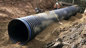
Backfill Placement
Bedding performs a most important function in that it levels out any irregularities in the trench bottom, assuring uniform support and load distribution along the barrel of each pipe section and supports the haunching material. A mat of at least 6 inches of compacted embedment material will provide satisfactory bedding.
Haunching material must be carefully placed and compacted so as not to disturb the pipe from its line and grade while ensuring that it is in firm and intimate contact with the entire bottom surface of the pipe. Usually a vibratory compactor has less tendency to disturb the pipe than an impact tamper.
Primary initial backfill should be placed and compacted in lifts evenly placed on each side of the pipe. The lifts should not be greater than 12 inches for Class 1, 8 inches for Class II, and 6 inches for Class III and IVa materials. The primary initial backfill should extend up to at least three-quarters of the pipe diameter to perform its function of pipe side support.
If the construction does not call for the use of a secondary initial backfill, then the primary layer should extend to not less than 6 inches above the pipe crown. In any location where the pipe may be covered by existing or future groundwater, the primary initial backfill should extend up to at least 6 inches over the pipe crown for pipe up to 27-inch diameter and to at least 12 inches over the pipe for larger pipe.
Secondary initial backfill serves to protect the pipe during the final backfilling operation and to provide support to the top portion of the pipe. Secondary initial backfill should extend to 6 inches above pipe for pipe up to 24 inches and to 12 inches for larger pipe.
These depths can be modified slightly depending on the depth of burial, groundwater level, and type of native soil. Compaction of this layer should be to the same extent as that specified for the primary initial backfill. If the final backfill material contains large rock (boulder or cobble size) or clumps, then 18 inches of cushion material should be provided in the secondary initial backfill.
Secondary initial backfill may consist of a different material than the primary initial backfill; however, in most cases, it should be a material that will produce an E’ of at least 750 psi. The final backfill may consist of any material that satisfies road construction or other requirements.
The material must be free of large stones or other dense hard objects which could damage the pipe when dropped into the trench or create concentrated pipe loading. The final backfill may be placed in the trench by machines. There should be at least one foot of cover over the pipe before compaction of the final backfill by the use of self-powered compactors.
Construction vehicles should not be driven over the pipe until a three foot cover of properly compacted material is placed over the pipe. When backfilling on slopes, the final backfill should be well compacted if there is any risk of the newly backfilled trench becoming a “french drain.” Greater compaction may be achieved by tamping the final backfill in 4 inch layers all the way from the top of the initial backfill to the ground or surface line of the trench.
To prevent water from undercutting the underside of the pipe, concrete collars keyed into the trench sides and foundation may be poured around the pipe or a PE waterstop can be fabricated onto the pipe.
Sunlight Exposure
Placing pipe that has been in direct sunlight in a cooler trench will result in thermal contraction of the pipe’s length. This contraction can generate force which could result in pull-out at mechanical couplings or other buried structures. Allow pipe to cool before making connections to an anchored joint, flange, or a fitting that requires protection against excessive pull-out forces.
Covering the pipe with embedment will facilitate cooling.
Cold (Field) Bending
Coiled lengths and long strings of PE fused pipe may be cold bent in the field. The allowable bend ratio is determined by the pipe diameter and the dimension ratio. Because fittings and flange connections are rigid compared to the pipe, the minimum bend radius is 100 times the pipe’s outside diameter (OD), when a fitting or flange connection is present in the bend.
The bend radius should be limited to 100 x OD for a distance of about 5 times the pipe diameter on either side of the fitting location.
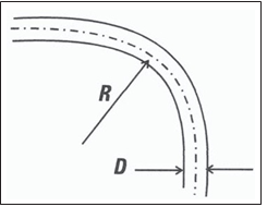
Minimum Bend Radius for PE Pipe Installed in Open Cut Trench
| Dimension Ration, DR | Minimum Cold Bend Radius |
| 7, 7.3, 9 | 20 x Pipe OD |
| 11, 13.5 | 25 x Pipe OD |
| 17, 21 | 27 x Pipe OD |
| 26 | 34 x Pipe OD |
| 32.5 | 42 x Pipe OD |
| 41 | 52 x Pipe OD |
| Fitting or flange present in bend | 100 x Pipe OD |
RELATED: Underground Installation Of Polyethylene Pipe – Part 1
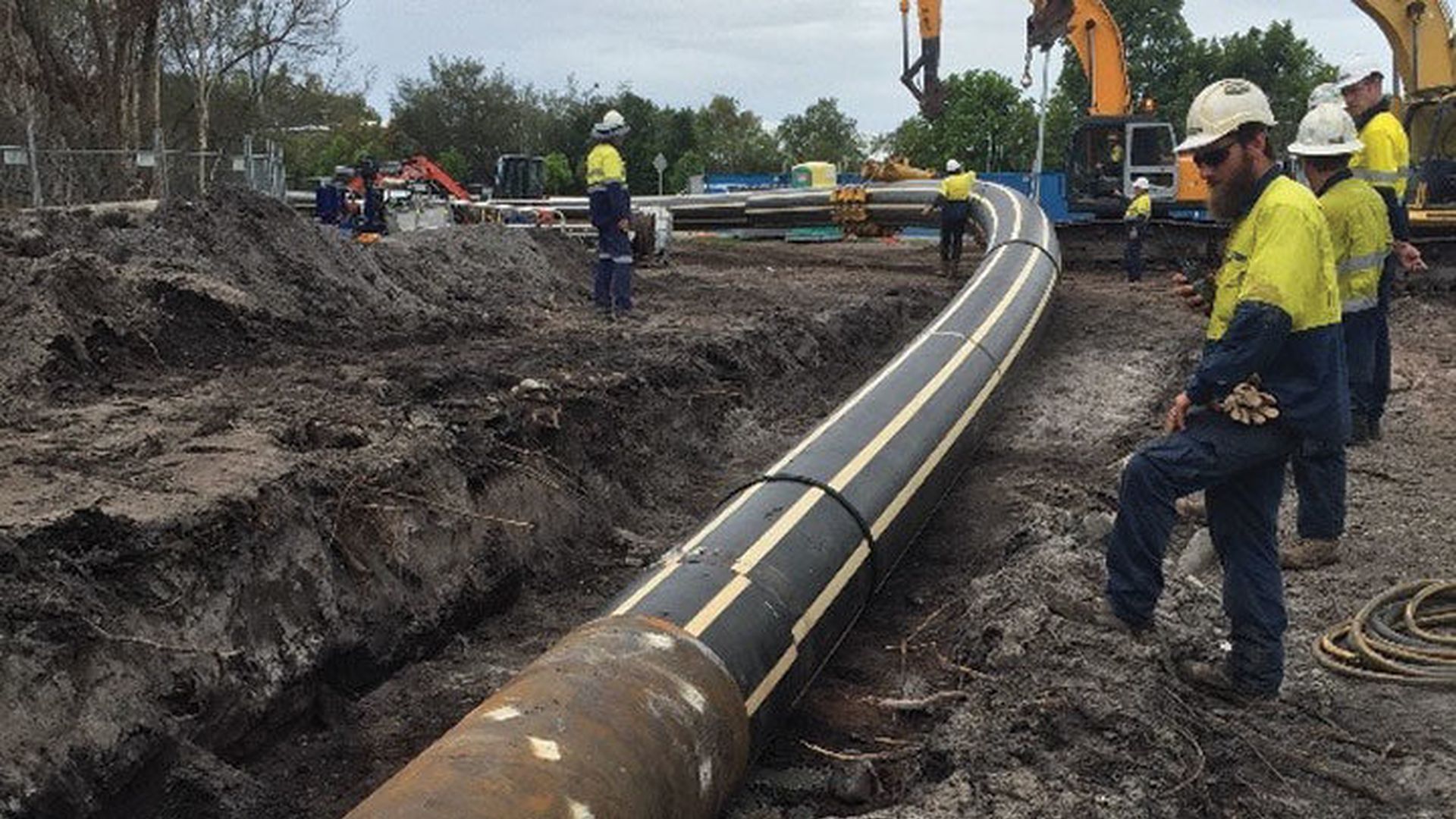
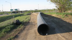
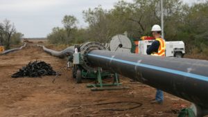
Installation of Pipe in Curves
Field bending involves excavating the trench to the desired bend radius, then sweeping or pulling the pipe string into the required bend and placing it in the trench. Temporary restraints may be required to bend the pipe, and to maintain the bend while placing the pipe in the trench and placing initial backfill.
Temporary blocks or restraints must be removed before installing final backfill, and any voids must be filled with compacted initial backfill material. Considerable force may be required to field bend the pipe, and the pipe may spring back forcibly if the restraints slip or are inadvertently released while bending. Observe appropriate safety precautions during field bending.
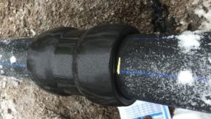
Transition from PE Pressure Pipe to Gasket Jointed Pipe
The heat fusion joint used for PE pipe creates an essentially continuous length of pipe. When the pipe is pressurized two significant internal forces are present in the pipe. End thrust from bends or end caps is transmitted through the pipe as a longitudinal force. Hoop stress (hoop thrust) occurs due to the internal pressure.
The longitudinal force tends to grow the pipe length while the hoop thrust expands the diameter (ever so slightly) and tends to contract the pipe’s length in proportion to Poisson’s Ratio. In an all PE pipe system the length effects from these two forces tend to cancel each other out. As a result, buried PE pipes are self-restrained and require no thrust blocking.
A different situation occurs when PE pipe transitions to a type of pipe material that is joined by non-restrained gasket joints. The longitudinal force may be no longer present. The result is that hoop expansion is unbalanced and will cause contraction of the PE pipe. This contraction can result in pulling apart of gasket joints in line with the PE pipe.
Generally, it is necessary to anchor the ends of a PE pipeline that transitions into an unrestrained gasket jointed pipe system. If the gasket joints are restrained anchoring is unnecessary.
Proper Burial of Fabricated PE Fittings
A common question is “Does the installation of heat fused PE solid wall pipe and fittings need thrust blocks?” The simple answer to this question is that heat fused PE pipe and fittings are a monolithic structure which does not require thrust blocks to restrain the longitudinal loads resulting from pipe pressurization.
Since fittings are part of the monolithic structure no thrust blocks are needed to keep the fittings from separating from the PE pipe. Bell and spigot piping systems must have thrust blocks or restrained joints to prevent separation of pipe from fittings when there is a change of direction.
Pipe movement due to elastic deformation, thermal expansion/contraction, etc. is not detrimental to PE pipe, but pipe movement or the attachment of valves or other appurtenances used with PE pipe systems can cause excessive loads. Proper backfill prevents excessive loads in most situations.
Common fittings, elbows and equal tees normally require the same backfill as specified for the pipe. When service connections are made from PE water mains, no special compaction is required. When service connections are made under an active roadway, 95% Standard Proctor density is normally required around the pipe and the service connection.
In water systems and fire protection piping systems, reducing tees are frequently used to connect from the main to valves and hydrants. While no true thrust blocks are on the PE pipe or fittings in this arrangement, the sand stabilized with cement provides proper support for the reducing tee.
Compaction of the soil around these fittings is difficult and the use of sand stabilized with cement or flowable fill is usually easy.
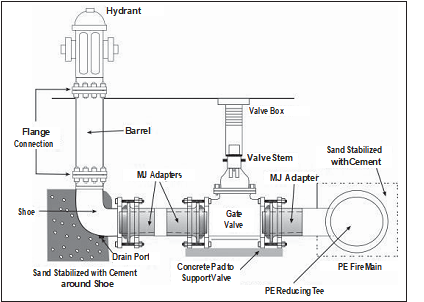
As with all piping systems, proper compaction of the soil around pipe and fittings is important. In water and/or fire protection systems, when in-situ embedment materials can be compacted to a Standard Proctor density of 85% for installation outside of roadways or 95% Standard Proctor density in roadways, these materials should be used. When in-situ materials do not provide proper support, then sand stabilized with cement or flowable fill should be used.
The above figure shows an PE self-restrained mechanical joint (MJ) adapter being used to connect to the valve. When large reducing tees or equal tees are used, MJ adapters, flanges or electrofusion couplings should be fused to the reducing tees before it is placed in the trench.
The direct connection of long pipe sections or valves can create bending loads on the leg of the reducing tee. The use of PE MJ adapters, flanges or electrofusion couplings on the reducing leg of the tee makes installation of reducing tees easier and safer while preventing stresses on the tee.
Inspection
The engineer should provide inspection commensurate with the application. Good inspection would include some or all of the following:
- Verification that all embedment materials meet the specification and verification of pipe grade and alignment,
- Verification that the correct pipe is installed (see numerical code printed on pipe),
- Observation of pipe installation, placement of embedment and backfill materials, and trench excavation methods,
- Verification that proper pipe storage and handling procedures are followed, that pipe placement in the trench, attachment of mechanical joints, fittings and appurtenances, and transitions to other pipes were done in accordance with recommended methods, that scratches or gouges do not exceed the permitted depth, and that the minimum bend radius was not exceeded,
- In the case of large diameter gravity pipes (gasket joined) inspection for deflection by either pulling a mandrel through the pipe or taking physical measurements of the pipe vertical diameter.
- In the case of pressure pipes record results of leak testing.
Appendix 1
Embedment Classification per ASTM D-2321
Pipe embedment materials have been grouped by ASTM D-2321-05, “Underground Installation of Flexible Thermoplastic Sewer Pipe”, into five general embedment classes based on their particle size (grain size) with the materials most suitable for use being assigned the lowest class numbers. Table A1 gives a summary of these groupings.
Embedment Classes for Plastic Pipes
|
Class |
Soil Description |
Soil Group Symbol |
| IA | Manufactured aggregate, angular open-graded and clean includes crushed stone,
crushed cinders or shells, contains little or no fines. |
None |
| IB | Processed aggregate, angular dense-graded and clean. Includes IA material mixed with sand and gravel to minimize migration. | None |
| II | Coarse-grained soils, clean. Includes gravels, gravel-sand mixtures, and well and poorly
graded sands. Contains little or no fines (less than 5% passing a #200 sieve.) |
GW, GP SW, SP |
| II | Coarse-grained soils, borderline clean to “with fines”. Contains 5% to 12% fines (passing #200). | GM-GC SP-SM |
| III | Coarse-grained soils containing 12% to 50% fines. Includes clayey gravel, silty sands,
and clayey sands. |
GM, GC SM, SC |
| IVA | Fine-grained soils (inorganic). Includes inorganic silts, rock flour, silty-fine sands,
clays of low to medium plasticity, and silty or sandy clays. |
ML, CL |
| IVB | Fine-grained soils (inorganic). Includes diatomaceous silts, elastic silts, fat clays. | MH, CH |
| V | Organic soils. Includes organic silts or clays and peat. | OL, OH PT |
Appendix 2
Basic Soil Concepts For Flexible Pipe Installation
Soil Classification
The embedment soil surrounding a flexible pipe prevents pipe from deflecting through its shear strength and stiffness. Shear strength enables the soil to resist distortion much like a solid body. Shear strength, or shear resistance as it is often called, arises from the structure of the soil’s fabric. Soil is an assemblage of mineral particles such as silica or aluminum silicates, water, and air.
Mineral particles can range in size from the large, such as boulders, to the microscopic, such as the colloidal particles making up clay. The size of the individual soil particles or grains has a significant effect on the soil’s behavior. Embedment soil is classified as either “fine” grained or “coarse” grained.
Fine Grain Soil (Clay and Silt)
Very small (colloidal) size soil particles are capable of absorbing large quantities of water, as much as 10 times their own weight. These particles attract each other to produce a mass which sticks together.
This property is called cohesion or plasticity. Soils containing such particles are referred to as “cohesive” and include clayey soils. Cohesion gives clayey soils resistance to shear. The strength of clayey soils is dependent on the amount of water within the soil.
As the content of water increases, the shear resistance decreases. Therefore, when using clays as pipe embedment beneath the ground water level, one must examine its sensitivity to water. Fat clays (CH), which are highly expansive, usually make poor embedment materials.
(CH is the USCF soil classification symbol for fat clay.) Lean clays (CL), or other clays having relative low sensitivity to water, sometimes can be used for embedment.
While silts possess little to no cohesion, they are composed of very fine grains, which makes them behave somewhat like clay in that they can contain a high percentage of water. It is also common for silt and clay to occur together.
Therefore, the general classification schemes for pipe embedment usually treat silts and clays similarly. (USCF symbols for inorganic silts are ML and MH, and for organic silts OL and OH.)
Coarse Grain Soils
Assemblages of larger-sized particles such as sands (S) and gravels (G) do not exhibit plasticity. Water has less effect on these materials. These soils are called “cohesionless” or “granular. ”
Normally, cohesionless soils have high shear resistances. When a mass of cohesionless soil is sheared, individual grains either roll, slide, fracture, or distort along the surface of sliding. Likewise, many cohesive soils contain grains of sand, so they can exhibit significant shear resistance. These materials make excellent embedment in wet or dry conditions.
Density and Compaction
When discussing the installation of embedment material, two terms are use extensively. They are compaction and density. These terms are defined, herein, to assist the reader. Density refers to the weight of a particular volume of soil As discussed above, soil consists of three materials or phases: a mineral phase, water, and air.
As the soil is compacted, the mineral phase may undergo some change, but typically the air and water are expelled from the soil and the overall volume is reduced. The weight of the mineral phase stays the same. Thus, a given weight of mineral phase occupies a smaller volume after compaction.
Typically, when densities are given, they are based on the dry unit weight of the soil (which is the weight of the mineral phase only) occupying a given volume, say a cubic foot. Compaction, on the other hand, refers to the amount of energy imparted into the soil to reduce its volume.
Typically, more energy, often called compactive effort, is required to increase the density of a fine grain soil than a coarse grain soil. One reason for this is that the fine grain soil has cohesion which must be overcome in order for the mineral phase particles to be pushed closer together.
Another reason is that it is harder to force the water out of a fine grain material because of its low permeability.
Methods of Measuring Density
There are two general categories of density measures. One method involves imparting a standard amount of energy into the soil, say a fixed number of blows with a specified weight. The Standard and Modified Proctor density tests are such methods.
The other measure involves comparing the in-place density with the most dense and least dense arrangement that can be achieve with that soil. An example of this method is the Relative Density test. The Proctor Density is the most common method used with pipe embedment and will be discussed in somewhat more detail.
Typically, a soil sample is taken from the embedment material and tested in the laboratory, where a precisely defined amount of compaction energy is applied to it, which compacts the sample to its Proctor density.
(This amount of energy is defined by the particular Proctor test, whether it is the Standard Proctor defined in ASTM D-698, “Standard Test Methods for Laboratory Compaction Characteristics of Soil Using Standard Effort (12 400 ft-lbf/ft3 (600 kN-m/m3)) or the Modified Proctor defined in ASTM D-1557, “Standard Test Methods for Laboratory Compaction Characteristics of Soil Using Modified Effort (56,000 ft-lbf/ft3 (2,700 kN-m/m3)).”
The sample is then dried and its density measured. This density is the standard for this material and is considered to be 100 percent of the Proctor density. The technician then makes measurement of the density (dry unit weight per cubic ft.) of the compacted embedment in the field using, say, the nuclear density gauge.
That density can then be compared with the density obtained in the laboratory. The comparison is usually expressed in percent. Typically, the field density must be at least 90 percent of the laboratory density. In this case, we would say the minimum density is 90 percent of the Proctor.
For pipe installation, the important factor is soil stiffness. If two soils are compacted to the same Proctor density, that does not mean that the two soils provide equal supporting stiffness for the pipe. A crushed stone at 90 percent Proctor will be much stiffer than a clay compacted to 90 percent Proctor.
This fact is illustrated by the different E’ values assigned to these materials at these densities. In the case of the crushed stone its E’ equals 3000 psi, whereas the clay has an E’ of only a 1000 psi. Methods used to measure soil stiffness such as the California Bearing Ratio test are not convenient for field testing of pipe. Therefore, it is common to measure and monitor density.
Comparison of Installation of Rigid and Flexible Pipe
The underground installation of PE piping is similar to the installation of other flexible piping materials. The performance of the pipe will depend on the quality of the installation. Most PE piping is considered flexible, which means that the pipe installed for non-pressure applications will depend to some extent on the support of the embedment soil.
Often the installation of flexible pipe is contrasted with the installation of rigid pipe, but general requirements for both types of pipe are similar. A narrow trench keeps loads on both types of pipe at a minimum. Both pipes require firm, stable bedding and uniform support under the haunches.
The major difference between the two types of pipes is that the flexible non-pressure pipe requires side support, whereas the rigid pipe does not. Side support comes from the placement of firm, stable material beside the pipe. Often this is the same material used beside the rigid pipe with the exception that the material must be compacted.
Sufficient space alongside the pipe must be provided for compacting the embedment material. The trench backfill placed above the pipe can be treated in the same manner for both flexible and rigid pipe. The denser the material above the pipe, the smaller the load applied to the pipe.
PE pipe interacts advantageously with the embedment soil. The viscoelastic properties of PE and most soils are similar. As the pipe deflects, much of the earth is transmitted by arching action to the soil around the pipe. Thus the need for stable soil beside the pipe. Rigid pipe is typically manufactured from materials that are not compliant with soil deformation.
As the soil settles, load accumulates on the rigid pipe. If this load exceeds the pipe materials’ yield strength, the pipe will fail by a sudden rupture or crack. PE is a ductile material that can yield. Under excessive loads, PE pipe will deform without cracking. The deformation is often sufficient to relieve the accumulated stresses, so performance is not interrupted.
Deflection is usually the main criterion for judging the performance of a gravity flow flexible pipe. Deflection is usually not much of a consideration for PE pipe installed for pressure applications unless they are in deep fill applications and have high DR’s.
Pipes that deflect have two advantages over rigid pipe: the deflection permits the release of accumulated stresses which promotes arching and causes a more uniform distribution of earth pressure around the pipe and the deflection affords a convenient method of inspecting the quality of the installation – generally the less deflection the better the installation.
Appendix 3
Pull-out of Mechanical Joints due to the Poisson Effect
When a tensile stress is applied to a material, the material elongates in the direction of the applied stress, and draws in at right angles to the direction of the applied stress. This relationship, called the Poisson effect, is a natural response to applied stress that occurs with all materials, but is particularly apparent with ductile materials.
For example, when a metal bar is pulled in a tensile test, it stretches out and necks down on the sides. Likewise, a rubber band elongates and necks down on the sides when it is pulled. When pipes such as polyethylene, PVC and metal pipes are pressurized, the diameter will expand slightly, and due to the Poisson effect, the pipe will shorten in length.
A pipe section with fully restrained joints such as a long string of butt-fused PE pipe will transmit Poisson effect pipe shortening from length to length through the restrained joints along the pipe string. Restrained joints include fusions, bolted flange connections, MJ adapter connections or other restrained mechanical connections.
If an unrestrained bell and spigot or mechanical sleeve joint is in-line with the restrained section, the cumulative Poisson effect shortening may cause in-line unrestrained joints or connections to be pulled apart. Therefore, unrestrained joints or mechanical connections that are in-line with fully restrained PE pipe must be either restrained or otherwise protected against pullout disjoining.
Connection Restraint Techniques
Adapters for Flanges and Mechanical Joints
Adapters are available for connecting PE pipe to flanges and to Mechanical Joints. Flange Adapters and MJ Adapters are fully pressure rated and fully restrained.
Flange Adapters and MJ Adapters are butt fused to the PE pipe, then connected to the mating flange or mechanical joint.
Plain-End PE Pipe Connections
When a plain-end PE pipe is inserted into a PVC or ductile iron bell or into a mechanical joint bell or component, a stiffener inside the PE pipe end and an external mechanical joint restraint are required. The internal stiffener must extend into the PE pipe end so that the stiffener supports the PE pipe under the seal and under the joint restraint clamp. The external restraint provides pullout resistance.
An ID stiffener and external mechanical restraint are required when plain end PE pressure pipe is connected to:
- Bell and spigot (push-on) joint in PVC pipe and ductile iron fittings, valves, hydrants and pipe;
- Bolted sleeve couplings;
- Mechanical joint pipe, fittings, valves and hydrants (when a MJ adapter is not used).
For PE butt fusion and where Flange Adapter and MJ Adapter fittings are used, ID stiffeners and external joint restraints are NOT required.
Pullout Prevention Techniques
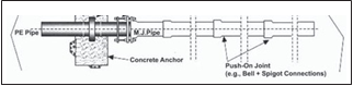
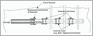
The transition region where a long PE pipe string is connected in-line to unrestrained piping can extend several joints into the non-PE pipe system because a restrained connection at the transition joint can transmit Poisson shortening to the next in line unrestrained joint in the non-PE pipe.
Typical pullout prevention techniques include restraining several non-PE pipe joints down line from the transition connection, or restraining the transition connection and installing an
in-line anchor in the PE pipe close to the transition connection. Figures A1 and A2 illustrate typical pullout prevention techniques.
Pullout Force
Poisson effect pipe shortening will occur whenever the pipe is pressurized. Because internal pipe pressures are higher during pressure testing and surge events, Poisson effect pipe shortening can be greater at these times compared to normal steady pressure operation.
Caution – Before pressure testing, all mechanical joint restraints must be completely installed and secured per manufacturer’s instructions, and concrete at in-line anchors and thrust blocking (if used) must be sufficiently cured and properly backfilled.
The Engineer should determine the Poisson Effect pullout force conditions that are appropriate for this application; then determine the appropriate techniques to protect unrestrained in-line mechanical connections against disjoining from Poisson effect pullout forces.
For a given PE pipe diameter and DR, approximate Poisson effect pullout force may be determined by multiplying the end area of the PE pipe by the product of the internal pressure hoop stress and the appropriate Poisson ratio.
Table below presents approximate Poisson effect pullout forces for selected sizes of PE pipe while operating at rated system internal pressure, during leak testing at 150% of rated system pressure and during a severe water hammer event while operating at steady pressure that causes a pressure surge to 200% of rated system pressure.
Approximate Poisson Effect Pullout Force
|
DIPS Pipe Size (DR 11) |
Approximate Pullout Force, lbs (a) | ||
|
Operating at Full Rated Pressure (b) |
During Pressure Tests at 150% of Rated Pressure (c) | Operating at Full Rated Pressure Plus Maximum Allowable Occasional Surge Pressure (d) | |
| 4” | 1,892 | 2,208 | 3,364 |
| 6” | 4,102 | 4,786 | 7,293 |
| 8” | 6,953 | 8,112 | 12,361 |
| 10” | 10,801 | 12,602 | 19,202 |
| 12” | 15,195 | 17,727 | 27,013 |
| 16” | 23,928 | 27,916 | 42,539 |
(a) Values for water at 73°F.
(b) Rated pressure for DR 11, Class 160 = 160 psi. Pullback force determined using long-term Poisson ratio of 0.45.
(c) Pullback force determined using short-term Poisson ratio of 0.35.
(d) Total pressure in pipe during surge event = 160 psi steady pressure + 160 psi surge pressure = 320 psi. Values determined by combining pullback force for steady pressure (long-term Poisson ratio of 0.45) plus pullout force for surge event (short-term Poisson ratio of 0.35).
Other longitudinal forces from thermal expansion and contraction, fluid thrust, or installation are not incorporated into table values.