PE piping is considered “flexible” pipe. Flexible pipes can deflect up to their allowable deflection limit without damage. Most PE pipes can withstand large amounts of deflection without damage but for practical purposes PE pipes are limited to 7.5% deflection or less depending on the DR and application.
For PE pipes, flexibility is directly proportional to the Dimension Ratio (DR). Low DR pipes such as DR 7.3 have high resistance to deflection because their flexibility is very low, or conversely their stiffness is high. DR 7.3 has a Pipe Stiffness (PS) per ASTM D2412 of about 1600 psi.
On the other hand DR 32.5 pipe has a PS of about 12.5 psi. Such a wide range in flexibility across a product line means different installation requirements for different DR’s may be necessary to achieve successful and economical installations.
The depth of cover and anticipated surface loads also affect the particular installation requirements. Therefore the engineer has to make an assessment of the application and site conditions to determine the best and most economical installation design.
In general there are two objectives to achieve in an installation. The first is to provide an envelope of embedment to protect the pipe from mechanical damage from impact or hard objects (cobbles, boulders) in the soil. The second is to provide support against earth and live load pressures, where this is required.
The envelope surrounding the pipe is referred to as the “embedment”. The earth and live loads are supported by the combination of the pipe’s stiffness and the embedment’s stiffness. Lower DR pipes will carry more of the load and require less support from the soil.
When support from the embedment is needed by the pipe to resist earth and live loads, the embedment material is often compacted. The trench backfill placed on top of the embedment material may also be compacted. Compaction of trench backfill immediately above the pipe facilitates the redistribution of some of the load away from the pipe and into the side-fill soil.
Terminology of Pipe Embedment Materials
The materials enveloping a buried pipe are generally identified, as shown by their function or location.
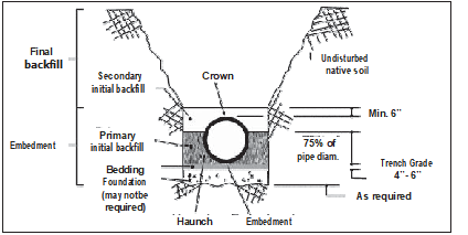
Note: When groundwater levels are expected to reach above the pipe, the secondary initial backfill should be a continuation of the primary initial backfill in order to provide optimum pipe support. Minimum trench width will depend on site conditions and embedment materials.
Foundation – A foundation is required only when the native trench bottom does not provide a firm working platform for placement of the pipe bedding material.
Initial Backfill – This is the critical zone of embedment soil surrounding the pipe from the foundation to at least 6 inches over the pipe. The pipe’s ability to support loads and resist deflection is determined by the quality of the embedment material and the quality of its placement. Within the initial backfill zone are bedding, haunching, primary, and secondary zones.
Bedding – In addition to bringing the trench bottom to required grade, the bedding levels out any irregularities and ensures uniform support along the length of the pipe.
Haunching – The backfill under the lower half of the pipe (haunches) distributes the superimposed loadings. The nature of the haunching material and the quality of its placement are one of the most important factors in limiting the deformation of PE pipe.
Primary Initial Backfill – This zone of backfill provides the primary support against lateral pipe deformation. To ensure such support is available, this zone should extend from trench grade up to at least 75 percent of the pipe diameter. Under some conditions, such as when the pipe will be permanently below the ground water table, the primary initial backfill should extend to at least 6 inches over the pipe.
Secondary Initial Backfill – The basic function of the material in this zone is to distribute overhead loads and to isolate the pipe from any adverse effects of the placement of the final backfill.
Final Backfill – As the final backfill is not an embedment material, its nature and quality of compaction has a lesser effect on the flexible pipe. However, arching and thus a load reduction on the pipe is promoted by a stiff backfill. To preclude the possibility of impact or concentrated loadings on the pipe, both during and after backfilling, the final backfill should be free of large rocks, organic material, and debris. The material and compaction requirements for the final backfill should reflect sound construction practices and satisfy local ordinances and sidewalk, road building, or other applicable regulations.
Engineered and Simplified Installation Guidelines for PE Pipe
The engineer must evaluate the site conditions, the subsurface conditions, and the application objectives to determine the extent of support the pipe may need from the surrounding soil.
Where the pipe burial depth is relatively deep, where subsurface soil conditions are not supportive of pipe, where surface loads or live loads are present, or where the pipe DR is high, the engineer will generally want to prepare a specific installation specification.
There are many applications that meet the criterion below for using Simplified Installation Guidelines. These applications would include many rural transmission and distribution water lines, many force main sewer lines, and many process water lines. Typically these lines contain pressure pipes installed at shallow depths which are sufficiently stiff to resist the minimal earth load.
In some cases a pipeline may contain sections that require specific engineering such as a section that crosses a road.
Simplified Installation Guidelines for Pressure Pipe
(Small diameter pressure pipes usually have adequate stiffness and are usually installed in such shallow depths that it is unnecessary to make an internal inspection of the pipe for deflection.)
A quality job can be achieved for most installations following the simple steps that are listed below. These guidelines apply where the following conditions are met:
- Pipe Diameter of 24-inch or less
- SDR equal to or less than 26
- Depth of Cover between 2. 5 feet and 16 feet
- Groundwater elevation never higher than 2 feet below the surface
- The route of the pipeline is through stable soil
Stable soil is an arbitrary definition referring to soil that can be cut vertically or nearly vertically without significant sloughing, or soil that is granular but dry (or de-watered) that can stand vertical to at least the height of the pipe. These soils must also possess good bearing strength.
(Quantitatively, good bearing capacity is defined as a minimum unconfined compressive strength of 1000 psf for cohesive soils or a minimum standard penetration resistance of 10 blows per ft for coarse grained soils.) Examples of soils that normally do not possess adequate stability for this method are mucky, organic, or loose and wet soils.
Where the above conditions are met, the specifier can write installation specifications from the following steps. The specifier should insure that all OSHA, state and local safety regulations are met.
The following are general guidelines for the installation of PE pipe. Other satisfactory methods or specifications may be available. This information should not be substituted for the judgment of a professional engineer in achieving specific requirements.
RELATED: Underground Installation Of Polyethylene Pipe – Part 2
Simplfied Step-by-Step Installation
Trenching
Trench collapses can occur in any soil and account for a large number of worker deaths each year. In unbraced or unsupported excavations, proper attention should be paid to sloping the trench wall to a safe angle. Consult the local codes. All trench shoring and bracing must be kept above the pipe.
(If this is not possible, consult the more detailed installation recommendations.) The length of open trench required for fused pipe sections should be such that bending and lowering the pipe into the ditch does not exceed the manufacturer’s minimum recommended bend radius and result in kinking.
The trench width at pipe grade should be equal to the pipe outer diameter (O. D.) plus 12 inches.
De-watering
For safe and proper construction the groundwater level in the trench should be kept below the pipe invert. This can be accomplished by deep wells, well points or sump pumps placed in the trench.
Bedding
Where the trench bottom soil can be cut and graded without difficulty, pressure pipe may be installed directly on the prepared trench bottom. For pressure pipe, the trench bottom may undulate, but must support the pipe smoothly and be free of ridges, hollows, and lumps. In other situations, bedding may be prepared from the excavated material if it is rock free and well broken up during excavation.
The trench bottom should be relatively smooth and free of rock. When rocks, boulders, or large stones are encountered which may cause point loading on the pipe, they should be removed and the trench bottom padded with 4 to 6 inches of tamped bedding material.
Bedding should consist of free-flowing material such as gravel, sand, silty sand, or clayey sand that is free of stones or hard particles larger than one-half inch.
Placing Pipe in Trench
PE pressure pipe up to about 8” in diameter and weighing roughly 6 lbs per ft or less can usually be placed in the trench by hand. Heavier, larger diameter pipe will require handling equipment to lift, move, and lower the pipe into the trench.
Pipe must not be dumped, dropped, pushed, or rolled into the trench. Appropriate safety precautions must be observed whenever persons are in or near the trench
Pipe Embedment
The embedment material should be a coarse grained soil, such as gravel or sand, or a coarse grained soil containing fines, such as a silty sand or clayey sand. The particle size should not exceed one-half inch for 2 to 4-inch pipe, three-quarter inch for 6 to 8-inch pipe and one inch for all other sizes.
Where the embedment is angular, crushed stone may be placed around the pipe by dumping and slicing with a shovel. Where the embedment is naturally occurring gravels, sands and mixtures with fines, the embedment should be placed in lifts, not exceeding 6 inches in thickness, and then tamped.
Tamping should be accomplished by using a mechanical tamper. Compact to at least 85 percent Standard Proctor density as defined in ASTM D698, Standard Test Methods for Laboratory Compaction Characteristics of Soil Using Standard Effort, (12 400 ft-lbf/ft3 (600 kN-m/m3)).” Under streets and roads, increase compaction to 95 percent Standard Proctor density.
Leak Testing
If a leak test is required, it should be conducted in accordance with the procedure in Chapter 2 after the embedment material is placed.
Trench Backfill
The final backfill may consist of the excavated material, provided it is free from unsuitable matter such as large lumps of clay, organic material, boulders or stones larger than 8 inches, or construction debris. Where the pipe is located beneath a road, place the final backfill in lifts and compact to 95 percent Standard Proctor Density.
Engineered Installation Guidelines for PE Pipe
There will be applications where the engineer will want to prepare a specific embedment specification. These applications would most likely include gravity flow pipes that are relatively deep, shallow cover applications where the pipe is subject to vehicular or train loading, pipes placed in unstable, soft, or wet soils, high DR pipes, and pipes in deep applications such as landfills and embankments.
The Simplified Installation Guidelines do not cover these applications. What all of these applications have in common is that the soil provides a relatively significant portion of the support against the overburden soil and surface loads. Or, to say this differently, the soil provides a relatively significant portion of the deflection resistance of the pipe.
In these cases, detailed attention must be paid to the native (in-situ) soil, the embedment soil, and the placement of the embedment soil. The objective of installation is to minimize pipe deflection. Profile wall pipes such as pipes manufactured to ASTM F894 are normally inspected for deflection after installation.
These pipes are normally limited to gravity flow applications and very low pressure systems. Conventionally- extruded, solid wall pipes such as “DR” classified pipes that are joined by heat fusion are normally not inspected for deflection. For instance AWWA standards C901 and C906 and manual M-55 do not call for field deflection testing of “DR” classified PE pipes.
Deflection Control
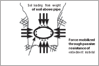
The load carrying capability of a PE pipe, particularly a pipe with a high DR, can be greatly increased by the soil in which it is embedded. When the pipe is loaded, load is transferred from the pipe to the soil by a horizontal outward movement of the pipe wall. This enhances contact between pipe and soil and mobilizes the passive resistance of the soil.
This resistance aids in preventing further pipe deformation and contributes to the support for the vertical load. The amount of resistance found in the embedment soil is a direct consequence of the installation procedure. The stiffer the embedment materials are, the less deflection occurs.
Because of this, the combination of embedment and pipe is often referred to as a pipe-soil system. The key objective of a PE pipe installation is to limit or control deflection. (The term “deflection” will mean a change in vertical diameter of the pipe, unless otherwise stated.)
The deflection of a PE pipe is the sum total of two major components: the “installation deflection,” which reflects the technique and care by which the pipe is handled and installed; and the “service deflection,” which reflects the accommodation of the constructed pipe-soil system to the subsequent earth loading and other loadings.
The “service deflection,” which is usually a decrease in vertical pipe diameter, may be predicted by a number of reasonably well documented relationships, including those of Watkins and Spangler or by use of a finite element analysis such as CANDE.
The “installation deflection” may be either an increase or decrease in vertical pipe diameter. An increase in vertical pipe diameter is referred to as “rise” and is usually a result of the forces acting on the pipe during compaction of the embedment beside it. Moderately stiff pipes such as DR17 and DR21 and stiffer pipes are usually unaffected by “rise” due to normal construction technique.
Up to a point this may be beneficial in offsetting service deflection. Installation deflection is not predictable by any mathematical formula, although there are empirical methods for accounting for it. Installation deflection is subject to control by the care used in the placement and compaction of the pipe embedment material in relation to the pipe’s ring stiffness.
For instance, compaction forces from hand operated air or gasoline tampers normally cause little rise, even when obtaining densities of 95 percent, but driving heavy loading equipment or driven compactors on the embedment while it is being placed beside the pipe may cause severe rise even in DR17 and stiffer pipes.
Commonly, deflection varies along the length of the pipeline due to variations in construction technique, soil type and loading. Field measurements illustrating this variability have been made by the U. S. Bureau of Reclamation and have been published by Howard(3). Typically, this variation runs around ±2 percent.
Deflection Limit
Field inspection of the installation procedure is generally adequate for controlling deflection of most PE fusion joined pipes. Very large diameter pipes (man entry) and gasketed jointed PE pipes are sometimes inspected for vertical deflection.
Typically deflection measurements are made only after the backfill has been placed on the pipe for at least 30 days. The engineer will specify an acceptance deflection. Commonly a limit of 5 percent is used. This provides an additional safety factor as most gravity flow PE pipe can withstand higher deflection without damage.
Pipe Embedment Materials
The embedment is the material immediately surrounding the pipe. This material may be imported, such as a crushed stone, or it may be the material excavated from the trench to make room for the pipe. In this case, it is referred to as native soil.
The embedment material should provide adequate strength, stiffness, uniformity of contact and stability to minimize deformation of the pipe due to earth pressures. The earth pressure acting on the pipe varies around the pipe’s circumference. The pressure on the crown or top will typically be less than the free field stress as is the pressure at the invert or bottom of the pipe.
Often, the highest pressure may be acting horizontally at the springline of the pipe, due to mobilization of passive pressure and arching. Because the earth pressure is acting around the circumference, it is important to completely envelop the pipe in embedment.
(This may vary to a greater or lesser extent depending on the earth pressure, burial depth, and SDR.) To ensure that the embedment function should always be carried out under the anticipated job conditions, the design engineer will specify the permissible pipe embedment materials and their minimum acceptable density (compaction).
The properties of the in-situ (or native) soil into which the pipe is placed need not be as demanding as those for the embedment materials (unless it is used as the embedment material). The native soil may experience additional compression and deformation due to the horizontal pressure exerted by the pipe and transferred through the embedment material.
This is usually a minor effect, but in some cases it can result in additional pipe deflection. This is most likely to occur where native soils are wet and loose, soft, or where native soil sloughs into the trench during excavation and is not removed. This effect is attenuated as the trench width (or width of embedment material) increases.
Therefore, consideration must be given to the in-situ soil to ensure that it has adequate strength to permanently contain the embedment system.
Classification and Supporting Strength of Pipe Embedment Materials
The burial of PE pipe for gravity flow applications is covered by ASTM D2321 “Standard Practice for Underground Installation of Thermoplastic Pipe for Sewer and Other Gravity-Flow Applications.” ASTM 2774, “Standard Practice for Underground Installation of Thermoplastic Pressure Piping,” covers water pipe and force mains.
Strength of Embedment Soil
When selecting embedment material, consideration should be given to how the grain size, shape, and distribution will affect its supporting strength. The following will help guide the designer or installer in making a choice. In general, soils with large grains such as gravel have the highest stiffness and thus provide the most supporting strengths.
Rounded grains tend to roll easier than angular, or sharp grains, which tend to interlock, and resist shear better. Well graded mixtures of soils (GW, SW), which contain a good representation of grains from a wide range of sizes, tend to offer more resistance than uniform graded soils (GP, SP).
Aside from the grain characteristics, the density has the greatest effect on the embedment’s stiffness. For instance, in a dense soil there is considerable interlocking of grains and a high degree of grain-to-grain contact. Movement within the soil mass is restricted as the volume of the soil along the surface of sliding must expand for the grains to displace.
This requires a high degree of energy. In a loose soil, movement causes the grains to roll or to slide, which requires far less energy. Thus, loose soil has a lower resistance to movement. Loose soil will permit more deflection of pipe for a given load than a dense soil.
Embedment Classification Per ASTM D-2321
Pipe embedment materials have been grouped by ASTM D-2321, “Standard Practice for Underground Installation of Thermoplastic Pipe for Sewers and Other Gravity –Flow Applications” into five embedment classes according to their suitability for that use.
Class I and Class II
Class I and II soils are granular and tend to provide the maximum embedment support as illustrated by the high E’ values that can be achieved with them. The relationship between soil types and E’ values. Class I material is generally manufactured aggregate, such as crushed stone.
Class II materials consist of clean sands and gravels and are more likely to be naturally occurring soils such as river deposits. Class I and Class II materials can be blended together to obtain materials that resist migration of finer soils into the embedment zone.
In addition, Class I and II materials can be placed and compacted over a wide range of moisture content more easily than can other materials. This tends to minimize pipe deflection during installation. The high permeability of open-graded Class I and II materials aids in de-watering trenches, making these materials desirable in situations such as rock cuts where water problems may be encountered.
This favorable combination of characteristics leads many designers to select these materials over others when they are readily and economically available. Maximum aggregate size of Class I and Class II materials when used next to the pipe (i. e. , bedding, haunching and initial backfill) should not be larger than those given in Table below.
(Larger stones up to 1½ inches have been successfully used, but they are difficult to shovel slice and compact.) The smaller the rock size, the easier it is to place in the haunches. Maximum size for the foundation material is not restricted except that it should be graded to prevent the bedding stone from migrating into it.
Maximum Particle Size vs. Pipe Size
| Nominal Pipe Size (in.) | Maximum Particle Size (in.) |
| 2 to 4 | ½ |
| 6 to 8 | ¾ |
| 10 to 15 | 1 |
| 16 and larger | 1 ½ |
Migration
When the pipe is located beneath the ground water level, consideration must be given to the possibility of loss of side support through soil migration (the conveying by ground water of finer particle soils into void spaces of coarser soils). Generally, migration can occur where the void spaces in the embedment material are sufficiently large to allow the intrusion of eroded fines from the trench side walls.
For migration to occur, the in-situ soil must be erodible. Normally, erodible soils are fine sand and silts and special clays known as dispersive clays. (Most clays have good resistance to dispersion.)
This situation is exacerbated where a significant gradient exists in the ground water from outside of the trench toward the inside of the trench; i. e. , the trench must act as a drain. (Seasonal fluctuations of the ground water level normally do not create this condition.)
For such anticipated conditions, it is desirable when using granular materials (Class I and II) to specify that they be angular and graded to minimize migration. Rounded particles have a tendency to flow when a considerable amount of water exists and material with a high void content provides “room” for migrating particles.
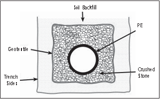
One approach to preventing migration is to use geotextile separation fabrics. The fabric is sized to allow water to flow but to hold embedment materials around the pipe.
Cement Stabilized Sand
One special case of Class II material is Cement Stabilized Sand. Cement Stabilized Sand, once cured, is generally considered to give the same or better supporting strength as compacted Class I material. Cement Stabilized Sand consists of sand mixed with 3 to 5 percent cement. To achieve proper density, the material is placed with compaction rather than poured as with concrete.
The material must be placed moist (at or near optimum moisture content) and then compacted in lifts as a Class II material. (The optimum moisture content is that moisture content at which a material can achieve its highest density for a given level of compaction.) If desired, deflection can be reduced if the cement sand embedment material is allowed to cure overnight before placement of backfill to grade.
If the trench is backfilled immediately, cement sand will give the same support as a Class II material, but the lag factor will be reduced. Cement sand is usually placed in both the primary initial and secondary initial backfill zones.
Class lIl and Class IVA
Class lIl and Class IVA materials provide less supporting stiffness than Class I or II materials for a given density or compaction level, in part because of the increased clay content. In addition, they require greater compactive effort to attain specified densities and their moisture content must be closely controlled within the optimum limit.
Placement and compaction of Class IVA materials are especially sensitive to moisture content. If the Class IVA material is too wet, compaction equipment may sink into the material; if the soil is too dry, compaction may appear normal, but subsequent saturation with ground water may cause a collapse of the structure and lead to a loss of support.
Typically, Class IVA material is limited to applications with pressure pipe at shallow cover.
Class IVB and Class V
Class IVB and Class V materials offer hardly any support for a buried pipe and are often difficult to properly place and compact. These materials are normally not recommended for use as pipe embedment unless the pipe has a low SDR (or high ring stiffness), there are no traffic loads, and the depth of cover is only a few feet.
In many cases the pipe will float in this type of soil if the material becomes saturated.
Compaction of Embedment Materials
Compaction criteria for embedment materials are a normal requirement in flexible pipe construction. Compaction reduces the void space between individual grains and increases the embedment density, thereby greatly improving pipe load carrying ability while reducing deflection, settlement, and water infiltration problems.
Compaction of the embedment often will increase the stiffness of the in-situ soil and provide a sort of pre-stressing for the embedment and in-situ soils. Because of these benefits compaction should be considered on all projects.
Density Requirements
The required degree of compaction for an installation will be set by the designer in consideration of height of cover, extent of live loading, water table elevation and soil properties. Generally, the “moderate” compaction requirements are quite satisfactory.
When compacting to this “moderate” level, it is suggested that the minimum target values for field measured densities be set as 90 percent Standard Proctor Density. This field density requirement will ensure that the actual densities will always be within the “moderate” range.
The Standard Proctor density of embedment materials is normally measured using ASTM D-698, “Standard Test Methods for Laboratory Compaction Characteristics of Soil Using Standard Effort (12 400 ft-lbf/ft3 (600 kN-m/m3)) while the Modified Proctor density is measured using ASTM D-1557, “Standard Test Methods for Laboratory Compaction Characteristics of Soil Using Modified Effort (56,000 ft-lbf/ft3 (2,700 kN-m/m3)).”
Compaction Techniques
Compaction of the embedment material should be performed by the most economical method available, consistent with providing uniform compaction and attaining the minimum specified density. Typical equipment used for compaction are hand held tamping bars, gasoline driven impact tampers (“whackers”), vibratory plates, and air driven impact tampers (“pogo sticks”).
With crushed stone, some degree of densification can be achieved by the technique of shovel slicing, which consists of cutting the soil with a shovel.

Compaction of the haunching material can best be accomplished by hand with tampers or suitable power compactors, taking particular care in the latter case not to disturb the pipe from its line and grade. In 36” and larger pipe, hand tampers are often used to reach under the haunches; they are then followed up with power compaction alongside the pipe.
When compacting the embedment near the pipe with impact-type tampers, caution should be taken to not allow direct contact of the equipment with the pipe. Avoid use of impact tampers directly above the pipe until sufficient backfill (usually 12”) has been placed to ensure no local deformation of the pipe.
Compaction of the embedment material alongside the pipe should not cause pipe to lift off of grade, but if upward movement occurs, reduce the compaction level below the springline or move the compactor away from the pipe toward the side of the trench.
Compaction of primary initial backfill should be conducted at, or near, the material’s optimum moisture content. The backfill should be placed in layers, or lifts, that are brought up evenly on both sides of the pipe, otherwise the pipe could be moved off alignment. Each lift should be thoroughly compacted prior to placement of the next layer.
The maximum lift height that will allow development of uniform density will vary depending on the material, its moisture content, and compactive effort. In general, maximum lifts of approximately 12 inches for Class I, 8 inches for Class II, and 6 inches for all others are adequate.
Compaction of Class I and II Materials
Compaction by vibration is most effective with granular (Class I and II) materials. Compaction of stone does not deform the stone but it does move it into a more compact or dense arrangement. In cases where the engineer specifies a minimum soil density of 90 percent of Standard Proctor or higher, as for installations under deep cover, mechanical compaction of Class I materials will be required.
Impact tampers will also increase the density of Class I and II materials, primarily due to vibration. Impact tamping also acts to drive the embedment into the in-situ soil, which stiffens the trench wall interface. For this reason, impact compaction of Class I material should be considered for any application where the pipe will be below the ground water table or where the stability of the in-situ soil is in question.
An alternate method of achieving compaction with Class I materials is shovel slicing. Materials having been shovel sliced thoroughly will generally yield a modulus of around 1000 psi. A few passes with a vibratory compactor will increase the density and modulus of soil reaction.
Mechanical compaction of Class II materials can be aided by slight wetting. When so doing, care must be taken not to saturate the material or flood the trench, particularly when the native trench material does not drain freely. Flooding can result in flotation of the pipe.
Compaction by saturation, also called flooding or water tamping, is sometimes used to compact Class II materials. This method of compaction rarely yields Proctor densities greater than 75 percent, and therefore it will generally not give an E’ of 750 psi or higher. Flooding is only suited for those applications where the pipe has sufficient internal supporting strength for the design load and does not depend on the soil for side support.
(When considering this method for embedment that must provide side support, a geotechnical engineer should be consulted.) Compaction by saturation is limited to applications where both the embedment soil and in-situ soil are free draining. Compaction should be done in lifts not exceeding the radius of the pipe or 24 inches, whichever is smaller.
Only enough water should be placed to saturate the material. It should be determined through proper monitoring that the desired level of compaction is being attained in each lift. Compaction by saturation should not be used in freezing weather. Water jetting, or the introduction of water under pressure to the embedment material, should not be used with plastic pipe.
Compaction of Class lIl and IV Materials
Compaction by impact is usually most effective with Class lIl and Class IVa materials. The use of mechanical impact tampers is most practical and effective. Depending on the embedment material, its moisture content, and lift height, several compaction passes may be required. A maximum lift height of 6 inches should be used when compacting by impact. Embedment density should be suitably monitored to ensure that specification requirements are met.
Density Checks
It is prudent to routinely check density of the embedment material. Typically, several checks are made during start-up of the project to ensure that the compaction procedure is achieving the desired density. Random checks are subsequently made to verify that the materials or procedures have not changed.
Checks should be made at different elevations of the embedment material to assure that the desired compaction is being achieved throughout the embedment zone.
Trench Construction
Trenches should be excavated to line and grade as indicated by contract documents and in accordance with applicable safety standards. Excavation should proceed upgrade.
Excessive runs of open trench should be avoided to minimize such problems as trench flooding, caving of trench walls and the freezing of trench bottom and backfill material, and to minimize hazards to workmen and traffic. This can be accomplished by closely coordinating excavation with pipe installation and backfilling.
Principal considerations in trench construction are trench width, stability of the native soil supporting and containing the pipe and its embedment soil, stability of trench walls, and water accumulation in the trench.
When encountering unstable soils or wet conditions, they should be controlled by providing an alternate foundation, sloping or bracing the trench walls, de-watering the trench bottom, or some other such measure.
Trench Width
Since flexible pipe has to support, at most, only the weight of the “prism” or vertical column of soil directly over the pipe, the precaution of keeping the trench as narrow as possible is not the concern that it is for a rigid pipe, which can be subjected to the weight of the soil beside the prism as well as the prism itself.
With PE pipe, widening the trench will generally not cause a loading greater than the prism load on the pipe.
Trench width in firm, stable ground is determined by the practical consideration of allowing sufficient room for the proper preparation of the trench bottom and placement and compaction of the pipe embedment materials, and the economic consideration of the costs of excavation and of imported embedment materials.
Trench width in firm, stable ground will generally be determined by the pipe size and the compacting equipment used.
The trench width may need to be increased over the values in the table below to allow for sufficient clearance between the trench sidewalls and the pipe for compaction equipment. Typically for large diameter pipe (18” and larger), this required clearance will vary from 12 to 18 inches. If two or more pipes are laid in the same trench, sufficient space must be provided between the pipes so that embedment material can be compacted.
Minimum Trench Width in Stable Ground vs. Pipe Size
| Nominal Pipe Size (in.) | MinimumTrench Width (in.) |
| < 3 | 12 |
| 3 – 24 | Pipe O. D. + 12 |
| > 24 – 63 | Pipe O. D. + 24 |
Note: Minimum trench widths do not apply to trenching techniques that use chain or wheel trenchers or plows to lay PE pipe. Chain and wheel trenching techniques feed PE pipe over the earth-cutting machine and lay the pipe immediately into the earth-cut.
These techniques use round-bottom chain or wheel trenching machines that match pipe radius and do not require extra trench width to place embedment in the pipe haunches below the pipe springline. Plowing techniques feed smaller diameter PE pipe or tubing through a chute that is integrated into an earth plow. Plowing may not require backfilling.
Trench Length
The table below lists the recommended lengths of trench openings for each placement of continuous lengths of fused pipe, assembled above the trench. When the trench sidewalls are significantly sloped, somewhat shorter trench openings may be used.
When space or ground conditions do not permit these suggested trench openings, the pipe lengths may be joined within the trench, using a joining machine or flanged couplings. When bell-and-spigot jointed pipe or flange-end pipe is used, the trench opening needs to be only long enough to accommodate placement and assembly of a single pipe length.
Suggested Length of Minimum Trench Opening (Feet) for Installation of Joined Lengths of PE Pipe
| Nominal Pipe Size (in.) | Depth of Trench (Feet) | |||||
| 3 | 5 | 7 | 9 | 11 | 13 | |
| ½ to 3 | 15 | 20 | 25 | 30 | 35 | 40 |
| 4 to 8 | 25 | 30 | 35 | 40 | 45 | 50 |
| 10 to 14 | 35 | 40 | 45 | 50 | 55 | 60 |
| 16 to 22 | 45 | 50 | 55 | 60 | 65 | 70 |
| 24 to 42 | – | 60 | 65 | 70 | 75 | 80 |
| 48 | – | – | 80 | 90 | 100 | 110 |
Stability of the Trench
Although the native soil in which PE pipe is installed need not be as strong and stiff as the pipe embedment materials, it should provide adequate support and stable containment of the embedment material so that the density of the embedment material does not diminish.
If the trenching conditions present construction problems such as trench sidewalls that readily slough off or a soft trench floor that will not support workers or compaction, it is termed unstable. The instability is usually a condition of the trench and not the soil. Most often the primary cause of the instability is high groundwater, not the soil.
Even soft or loose soils can provide good support for the pipe if they are confined. The problem with unstable conditions generally occurs during the installation. When the trench is opened where groundwater is present, most soils, except firm, cohesive soils (firm clays) or cemented soils, tend to slough off the trench wall.
This results in a trench that keeps widening, with loose material falling into the trench floor. Soil formations that commonly lead to unstable trenching conditions include materials with fine grain soils (silts or clays) saturated with water and uncemented sands saturated with water.
In some cases, where the soil has an extremely high water content, such as with peat or with clay (or silt) having a water content beyond the liquid limit, the soil behaves “hydraulically”, that is, the water in the soil controls the soil’s behavior.
Here, the backfill must be designed to sustain all the pressure from the pipe without support from the in-situ soil. These conditions may occur in saturated fine grained soils where the unconfined compressive strength of the soil is less than 500 psf, or in saturated, sandy soils where the standard penetration value, N, is less than 6 blows per ft.
In this case, an engineering evaluation should be made to determine the necessity for special procedures such as a “wide” trench or permanent trench sheeting of the trench width. As mentioned above, most trench stability problems occur in trenches that are excavated below the groundwater level.
(However, the designer and the contractor should keep in mind that all trenches pose the risk of collapse and therefore workers should not be in trenches that are not adequately braced or sloped.)
Stability can be improved by lowering the water table through deep wells, well-points, or other such means. In some ground the permeability is such that the only option is to remove the water after it has seeped out of the trench walls. Here the contractor will use underdrains or sumps on the trench floor.
De-watering should continue throughout the pipe laying operation until sufficient cover is placed over the pipe so that it will not float.
Stability of Trench Floor
Trench floor stability is influenced by the soils beneath the trench. The floor must be stable in order to support the bedding material. A stable bedding minimizes bending of the pipe along its horizontal axis and supports the embedment enveloping the pipe. Generally, if the trench floor can be walked on without showing foot prints it is considered stable.
In many cases the floor can be stabilized by simply dewatering. Where dewatering is not possible or where it is not effective, stabilization of the trench floor may be accomplished by various cost-effective methods which can be suited to overcome all but the most difficult soil conditions.
Included among these are the use of alternate trench foundations such as wood pile or sheathing capped by a concrete mat, or wood sheathing with keyed-in plank foundation; stabilization of the soil by the use of special grout or chemicals; geofabric migration barriers; or ballasting (undercutting).
A cushion of bedding material must be provided between any special foundation and the pipe. Permanently buried timber should be suitably treated. Stabilization by ballasting (undercutting) is the removal of a sufficient quantity of undesirable material. This technique is frequently employed to stabilize randomly encountered short sections of unstable soil.
The extent of required over-excavation and details of accompanying construction requirements will be determined by the engineer in consideration of the qualities of the unstable soil and the specific design requirements. The following are general guidelines.
- The trench bottom should be over-excavated over the full trench width from 18 to 36 inches below the pipe grade (depending on the soil strength and pipe diameter) and then brought back to grade with a foundation of ballast material topped with Class I material.
- An appropriate bedding should then be placed on the foundation. The grading of the foundation material should be selected so that it acts as an impervious mat into which neither the bedding, other embedment material, nor the surrounding native soil will migrate.
These guidelines are suitable for most situations except for extremely weak soils (such as quicksands, organic silts, and peats) which may call for further overexcavation, or other special treatment.
Stability of Trench Walls
In order to control deflection, the embedment material must be placed from undisturbed trench sidewall to undisturbed trench sidewall. Where trench walls are unstable, it may be necessary to use trench shields, bracing, or permanent sheeting to achieve a stable sidewall while installing the pipe.
Where material sloughs into the trench it should be removed. This technique often leads to widening the trench. Walls of trenches below the elevation of the crown of the pipe should be maintained as vertical as possible.
The shape of the trench above the pipe will be determined by the stability of the trench walls, excavation depth, surface loadings near the trench, proximity of existing underground structures, presence of groundwater or runoff water, safety and practical considerations.
These will determine if the trench walls may be vertical, excavated with slope or benched sides, or shored. When trench walls are shored or otherwise stabilized, the construction scheme must allow for the proper placement and compaction of pipe embedment materials. Some suggested trench construction schemes follow. The final procedure must be in compliance with all applicable safety regulations.
Sloping of trench walls in granular and cohesionless soils should be provided whenever the walls are more than about four feet in depth or otherwise required by state, local or federal regulations. For safety, if the walls are not sloped, they should be stabilized by alternate means such as shoring or bracing.
The slope should be no greater than the angle of repose of the materials being excavated and should be approved by the engineer.
Shoring or bracing will frequently be required in wet fine grained cohesive type soils and clays. Bracing or sheathing that is constructed of treated timber, steel or other acceptable material may be used to stabilize trench walls either permanently or temporarily.
Wherever possible, sheathing and bracing should be installed so that its bottom extends no lower than about one-quarter of the pipe diameter below the pipe crown. When so installed, pulling the sheathing will minimally disturb the embedment material and the side support it provides.
Sheathing that is installed to project below the pipe springline should be left in place unless, as with some thinner sheathing, it is designed to be pulled and removed without disturbing the embedment next to the pipe.
In this case, the trench width should be increased by 12 to 24 inches depending on the pipe diameter to allow for minor disturbance to the embedment near the sheathing. Vibratory placement or extraction of sheeting is not advised. This method can cause severe disturbance to the bedding and liquefaction of the surrounding soils.
Where steel sheet piling is used as sheathing and is to be removed or pulled, to minimize disturbance to the pipe embedment, it should be installed so that it is not closer than one pipe diameter or 18 inches, whichever is larger, from either side of the pipe. The void left by removal of the sheathing should be filled with embedment material.
Portable Trench Shield
Portable trench shields or boxes which provide a moveable safe working area for installing pipe can be used with flexible pipe. However, the installation technique of flexible pipe with the shield is not the same as it is for rigid pipe. In order to use the shield with PE pipe, all excavation of the trench below the pipe crown elevation should be done from inside of the shield.
That is, the backhoe operator should dig inside of the shield and force the shield down as soil is removed. (The technique of digging out a large hole to pipe invert grade then sliding the shield into it will result in excess deflection of PE pipe and therefore, should not be used.)
After placing the pipe in the trench, embedment material should be placed in lifts and the shield vertically raised after each lift is placed so that workers can shovel embedment material under the shield to fill the void created by the shield wall.

If trench soil quality and applicable safety regulations permit, it is best to use shields that are placed with no portion of their sides extending lower than one-quarter of a pipe diameter below the pipe crown. This minimizes the amount of lifting required and precludes the possibility for disturbing embedment materials.
If the sides of the trench box or shield do project below this point, then the box should be lifted vertically as described above, before moving along the trench. The minimum inside clear width of the box, or shield, should allow for the minimum trench width requirements for the pipe to be satisfied plus an additional 12 to 24 inches depending on the pipe diameter.
