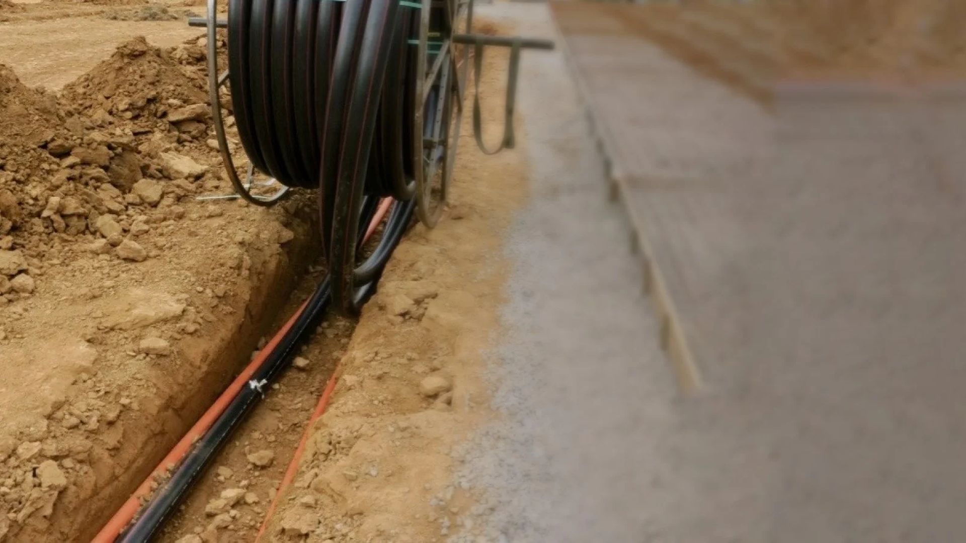
HDPE conduit can be wound onto reels with conduit lengths several thousand feet long. The length and flexibility allow navigation around unexpected obstructions below ground or within existing ducts and casings. Therefore, manufactured bends or elbows can be virtually eliminated.
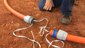
The few joints that are required can be made reliably through a number of options. HDPE conduit is suitable for all methods of duct and cable installation, including trenching, direct plow and installation into existing populated larger conduits and casing pipes.
Also, the flexible nature of HDPE conduit facilitates directional bore installations to traverse under obstacles like rivers or highways. Special HDPE products and accessories are also available for above ground or aerial applications.
Below Ground Installation
Generally, the three primary underground installation (or “OSP/Outside Plant”) methods are trenching, plowing and boring, described in general terms below. Conduits intended for buried applications are commonly differentiated into two classes, rigid and flexible, depending on their capacity to deform in service without cracking, or otherwise failing.
HDPE conduit can safely withstand considerable deformation without fracturing and is, therefore, classified as a flexible conduit. Flexible conduits deform vertically under earth load and expand laterally into the surrounding soil. The lateral movement mobilizes the soil’s passive resistance forces, which limit deformation of the conduit.
The accompanying vertical deflection permits soil-arching action to create a more uniform and reduced soil pressure acting on the conduit. HDPE stress relaxes over time to decrease the bending moment in the conduit wall and accommodates local deformation (strain) due to imperfections in the embedment material, both in the ring and longitudinal directions.
The relationship between pipe stiffness, soil modulus (stiffness), compaction and vertical loading is documented by the work of Spangler and Watkins. The pipe stiffness, as measured by ASTM D2412, and Spangler’s Iowa formula provide a basis for prediction of conduit deflection as related to dimension ratio and resin modulus.
It should be noted, however, the duration of loading affects the pipe stiffness, so the long-term modulus should be used. Flexible conduit has the potential to fail due to stress cracking when localized forces (for example, from a large sharp rock) exceed the material’s ability to relax and relieve stress.
Although current HDPE resins suitable for conduit applications have excellent stress relieving properties to avoid these failures, the design process should include consideration of the conduit resin’s stress crack resistance, as well as the selection of appropriate embedment material and compaction.
Trenching Methods
There are many variations on trenching installations, but generally the two main variations are the traditional “open trench” method and “continuous” trenching.
Open Trench/Continuous Trench
As the name implies, open trench installations involve digging an open trench using a backhoe, laying the conduit directly into the trench, and then placing an initial cover using the appropriate embedment material. Use of the appropriate embedment material and compaction to cover 6-8 inches over the conduit crown is critical to protect the conduit from damage due to the surrounding soil.
In Continuous Trenching, the conduit payoff moves along with the trenching process. This installation is accomplished with specialized trenching machines that cut the trench and remove the soil in a single action and can be used to place multiple conduits over long or short distances.
Digging the Trench
The trench should be dug as straight, level and free of protrusions as possible. Avoid direction changes tighter than the conduit’s allowable bend radius. When field forming a bend for a change in trench direction undercut the inside corners to assure the radius of the bend is correct.
Should there be a significant grade change, slope the trench bottom leading into and out of the grade change to support the conduit and maintain a recommended bend radius. Perpendicular trenches to the main trenchline may be required for connections to access or enclosure locations.
Trench intersections should be excavated to provide adequate space to make sweeping bends to assure the minimum bend radius is not exceeded for the conduit. Excavate the trench to the desired depth, and remove all rocks and large stones from the bottom of the trench to prevent damage to the conduit.
Push some clean fill (fine material, without stones) into the trench and compact to provide a firm level trench bottom for the conduit as it is installed in the trench.
Placing the conduit
A good practice to ensure long-term protection of underground facilities is to utilize proper bedding for conduit. Sand or gravel provides a more stable embedment around the conduit, protection against damage from sharp rocks, and allowing water to drain away from conduit easily.
An important consideration for open-trench installations of HDPE conduit is that conduit should be straightened to remove any residual “coil memory”. Coil memory can create a helical path as the conduit is placed in an open trench.
If installed and left unaddressed, this will cause greater resistance during cable installation, and shorten the cable installation lengths that can be accomplished.
Conduit pay off can be accomplished by pulling the conduit into the trench from a stationary reel or by laying the conduit into the trench from a moving reel, usually attached to a trailer. Laying the conduit out along the trench path prior to installation can help to reduce coil memory by allowing it to relax.
Care should be taken to pull off the conduits slowly to prevent them from overturning creating excess slack as the conduit is “paid-out” possibly causing the conduit to become tangled. Spacers should be used when placing multiple ducts in a trench. Spacers organize and prevent the ducts from twisting over and around each other.
By keeping the ducts in straight alignment, cable-pulling tensions will be reduced. When water is present in the trench, or when using extremely wet concrete slurry, floating of the conduit can be restricted through the use of anchored spacers.
Backfilling
It is best to place the select soil, free of large rocks or clumps and that is easily compacted, directly on and around the conduit to a height of 6 inches over the conduit crown. DO NOT place large rocks directly on the conduit. Allow at least 6 inches (15.3 cm) of clean, uniform soil above the conduit crown, after which the natural backfill can be returned to the trench.
The apparent change in soil condition also provides warning as any digging nears the conduit structure. This should not replace the practice of placing warning tape, but rather should serve as a supplement. Fill the trench and compact as required to provide compaction and prevent the trench backfill from settling.
During backfill, warning tape should be placed typically 1 to 3 feet above the conduit.
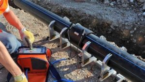
Direct Plow
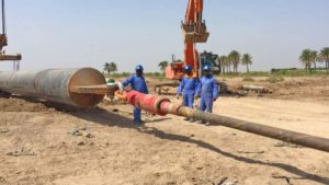
Plowing is the preferred installation for long continuous runs where soil conditions, space and an unobstructed route permit (e.g. in rural areas). Plowing installations use a plow blade (pulled by a tractor or mounted to a railroad car) to cut a furrow in the earth and place the conduit at the required depth through the plow’s chute.
The key distinction between plowing and continuous trenching is that trenching involves the actual removal of soil from the trench, whereas plowing only displaces soil as the plow is dragged through the ground while laying-in the conduit.
Consult the equipment manufacturer for specific recommendations on plow blade and feed tube designs. It is strongly recommended to have a professionally engineered single or double feed tube plow blade with a tube at least 0.5 inch (1.25 cm) larger than the largest conduit size and a radius no smaller than the minimum bend radius of the largest conduit size.
Experts use pipe design and soil mechanics to show SDR13.5 or heavier wall conduit is adequate to resist the compressive forces generated by external soil loading. However, in plowing installations, the significant bending over the dozer and through the plow test the deflection and buckling resistance of the conduit.
Therefore, a minimum SDR11 is recommended for plowing installation. Where rocky soils are encountered, SDR9 or heavier conduit should be considered to overcome uneven and point loading. Local regulation may require for a warning tape to be plowed in simultaneously at a depth of 1-3 feet above the crown of the conduit.
Most plow manufacturers make plow blades capable of burying the HDPE conduit and tape at the same time.
Plowing Variations
There are several variations of plowing installations. A few are described briefly below:
Vibratory Plowing – This method uses a vibrating blade and may allow use of a smaller tractor than used for static plowing.
- Rip and Plow – This method may be required when significant obstructions (for example, roots) are anticipated and uses an additional lead plow (without conduit) to cut an initial furrow in the ground and clear obstructions ahead of the primary plow with conduit.
- Pull-Plow Method – Instead of installing from a reel fed down through the plow chute, conduit is pulled from a stationery reel behind the plow as the furrow is cut. Typically for this method the plow blade is designed with an expander for creating a hole ahead of the conduit as it is being pulled into place.

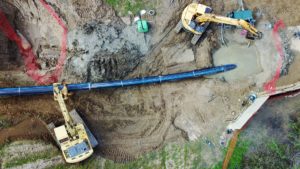
HDD (Horizontal Directional Drilling) aka “Directional Bores”
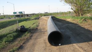
HDD allows the installation of conduit under obstacles that prevent use of the plowing or trenching installation methods, for example under rivers or highways. The HDD method has become ubiquitous in urban areas where trenching would cause severe disruption to traffic and cause significant restoration costs.
This installation method capitalizes on several unique features of HDPE conduits. These features are flexibility, tensile strength and long lengths enabling directional bores over very long distances. HDD is accomplished using a steerable head drilled through the earth to create a pathway for the conduit.
The equipment operator can control the depth and direction of the bore. Designing the directional drilling pathway should include consideration of tensile forces and bend radii to which the conduit will be subjected.
Flexible conduits installed in continuous lengths are susceptible to potential tensile failures if the wall thickness is under designed. The allowable tensile force (aka “safe pull strength”) is calculated based on the yield strength of HDPE with a safety factor. The engineer should also account for the allowable bend radius, especially on unsupported bends to prevent ovalization and kinking.

For conduit installation, HDD methods are, by definition, “mini-HDD” meaning the diameters are limited to less than or equal to 8 in. and the bore lengths of less than 1,000 ft. This contrasts with “maxi-HDD” where pipe diameters can exceed 30 in. and lengths can be measured in miles.
Mini-HDD for conduit design is based on less investigative information and therefore is more conservative.
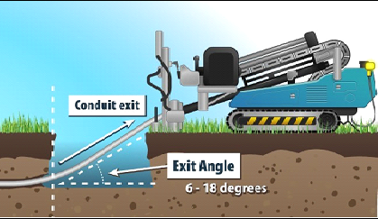
Setback
Generally, the setback distance is governed by the site conditions, the drill rod diameter (larger diameter drill rods have less curvature than small diameter drill rods), the allowable entry angle and the depth of the bore path. Position the machine back far enough so the maximum bore depth can be obtained without over-bending the drill string or the HDPE conduit being installed.
Depending on the rig size and entry angle, the distance may vary from 3-20 ft. (1-6 m) behind the entry point. The distance between the leading edge of the machine and the point where the drill pipe enters the ground should be as short as possible.
The entry angle is usually 8-16 degrees, although entry angles up to 20 degrees have been used on some larger diameter projects.
Drilling Fluids
Friction from the drilling and backreaming process creates heat. Drill head tracking electronics are sensitive to high temperatures and must be protected. Heat will build up if a constant flow of drillings fluids out of the annular space is not maintained. Moving the drill head in the bore path without the use of drilling fluid may also build up damaging heat, reducing component life.
Soils that are cut away by the drill bit or the backreamer must be moved in order to make room for the HDPE conduit. The drilling fluids mix with cuttings into a flowable slurry that can be moved out of the bore path during the backreaming step.
Drilling fluids maintain the integrity of the bore path especially in loose or soft soils. An example is bentonite slurry in sandy soils. The bentonite forms and stabilizes the bore wall to help prevent the walls along the bore path from caving-in around the drill string or HDPE conduit as it is being pulled back through.
Additionally, drilling fluids provide the necessary lubrication to enable the conduit to slide with less friction in sticky soils, such as clays and silts. The drilling fluid significantly reduces friction and the amount of torque required to rotate both the drill rod and backreamer. Drilling fluids also cool and reduce frictional wear on the drilling components extending their useful life.
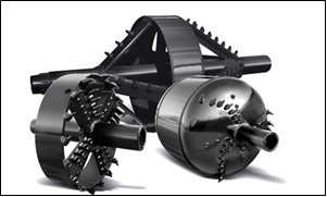
Backreaming
The function of the backreamer, is two-fold; 1) enlarging the bore hole size enough to allow for the pullback of conduit or bundle of conduits, and 2) mixing and removal of the bore hole cuttings with the bentonite slurry. The result is a borehole with bentonite slurry large enough to accommodate and lubricate the conduit package on the pull back.
The backreaming process is essential to the successful completion of the bore. Not only is it necessary to use the proper drilling fluid, it is also important to use the adequate amount of drilling fluid. Good slurry flow requires, at a minimum, a 50/50 ratio of drilling fluids to solids.
A higher drilling fluid to solids ratio can be beneficial especially in drier, more reactive soils.
Torque Limiter
The drill rig torque limiter’s essential function is to ensure the drill will not build excess thrust/rotation pressures over what the operator has deemed and selected as the drill limits (i.e., red lines). It is critical to note that these limits measure system pressure at the rig and not at the connection point (e.g., break-away swivel or product connection) and should not be confused with the tensile pullback forces being experienced by the conduit.
Overstressing the conduit (pulling stresses higher than the safe pull (tensile) strength) is one of the results of a failed bore installation. As the pullback progresses and more conduit is in the ground, bore pullback forces could increase as well.
Innerduct Installation into Existing Conduit or Casing (Conduit Network Pulling)
A large conduit can be subdivided by pulling in several smaller conduits (innerducts). These innerducts provide opportunity for multiple network owners along the pathway. Some innerducts can also be left empty for future cable placement or populated with fiber cable but not “lit” (known as dark fiber).
In the telephone and electrical utility industries, the underground network is often comprised of 3, 4, and 6 in. conduit banks. These “rigid” conduits are constructions of clay tile, cement conduit, or more recently, PVC conduit. They are usually separated by manhole vaults or buried pull-boxes.
Department of Transportation (DOT) regulations often require casing pipes as additional protection for buried conduits in road bores and traffic areas. Although steel casings have been used in the past, it is becoming more prevalent to horizontally bore under roadways, or waterways, and pull back an HDPE casing into which HDPE innerducts are installed.
The placement of manholes and pull-boxes and distances between them are largely a function of the following constraints:
• Location of branch circuit intersections
• Lengths of cables (or innerducts) available on reels
• Physical access limitations
• Path difficulty for placement of cable or innerducts
• Surface environment
• Method of cable placement (mid-assist access)
There are a number of variables that influence loading and selection of innerducts when pulling into conduit structures:
• Diameter of conduit and innerduct, and number of innerducts to be installed
• Clearance or fill ratio
• Length of the conduit run
• Direction changes of the conduit run, i.e. sweeps
• Type of pipe casing, which determines the coefficient of friction between the casing and innerducts
• Jam ratio combinations, see Section 8.1.1
• Pull speed and temperature
• Elevation and innerduct weight
Some direction on pull placements of inner ducts can be learned from traditional cable placement methods.
Preparation
Before placement of the innerduct inside the conduit can be started, it is important to have all of the necessary equipment to protect the innerduct. The use of sheaves, bending shoes, rolling blocks (45 and 90 degrees) and straight pulleys are required for protection of the innerduct during installation.
It is important that they all meet the proper radius for the innerduct size. The use of a pulling lubricant will greatly reduce the tension and stress on the innerduct as it is being pulled into an existing conduit. Ball bearing swivels are needed for attaching the winch line to the innerduct harness system.
Proofing
An important step that should be taken prior to innerduct installation is “proofing” the existing conduit to ensure that all obstructions are cleared and that pathway continuity and alignment is acceptable. It is recommended that a flexible proofing mandrel roughly 80% of the inner diameter of the casing pipe be pulled through prior to placing the innerduct.
For shorter run lengths, proofing conduit can also be performed by pushing a fiberglass fish and pulling back a flexible mandrel that has been attached to the fish tape end. Any problem areas should be felt as the fish tape is pulled back and should then be marked on the fish tape so that the distance to the problem is recorded and, if necessary, can be located for repair.
If the fiberglass fish makes its way through the conduit without any difficulties then the conduit has “proofed-out” and no repairs should be necessary.
Friction Considerations and Length Recovery Allowance
The stress of pulling innerduct through existing conduit will vary. Factors such as the length of the route, the number of directional changes, along with the age and condition of the conduit will contribute to the amount of friction. As innerduct is being pulled into place these factors are critical to determining the amount of lubrication to be used.
The effect of the pulling stress will cause the innerduct to elongate (i.e., stretch) in proportion to the amount of stress, but should be no more than 5% of the total length placed provided the innerduct is not over stressed as it is pulled into place.
For this reason, it is important to monitor the tensile load being placed on the innerduct during installation. Accounting for elongation is important by pulling additional slack to compensate for the distance the conduit ends will pull back during recovery to the original length.
If possible allow the conduit to relax over night to assure full recovery prior to cutting and coupling.
Above Ground/Aerial
There are many applications for aerial conduit, which include, but are not limited to, road crossings, rail crossings, trolley line crossings, and water crossings. Aerial conduit provides an efficient means of supporting and protecting cable. It also provides one or more pathways for easily replacing and adding cables without requiring encroachment in often hazardous or difficult to access locations.
A critical consideration for aerial applications is UV protection. For this reason, only conduit materials with special carbon black pigments should be used. Please refer to the applicable conduit product standard for more information on UV protection.
Installation
There are two preferred methods for aerial installation of conduit. One is the back-pull method from a stationary reel up into place through a series of pre-positioned blocks and rollers along the route. The other is the drive-off moving reel method where the conduit is hoisted up into position at various intervals.
Circumstances at the construction site and equipment/manpower availability will dictate which placement method to use.
Expansion/Contraction Considerations
As a rule of thumb, exposed conduit that is unrestricted can expand or contract about 1 in. for every 10 °F change in temperature for every 100 feet in length. For lashed conduit, there is a greater likelihood of conduit to move within the lashing. Therefore, design consideration must be given to the expansion/contraction potential of the HDPE conduit.
Expansion/contraction concerns are less likely with the use of self-supporting conduit because the conduit is integrally connected to the steel strand which helps restrict the movement of the conduit.
Back-Pull/Stationary Reel Installation Method
The back-pull from a stationary reel method is the usual method of aerial conduit placement. This method is also best suited for locations where the strand changes from the field side of the pole to the street side of the pole and where there are excessive obstacles to work around.
The conduit is run from the reel up to the strand, pulled back by an overlash cable puller that only travels forward and is held aloft by the cable blocks and rollers. Once the section of conduit is pulled into place, it is lashed and then cut.
Drive-Off/Moving Reel Installation Method
The drive-off/moving reel method may realize some manpower and time-saving in aerial conduit placement and lash-up. This method is used where there is existing strand and it is on one side of the poles, typically roadside. The conduit is attached to the strand and payed off a reel moving away from it. The conduit is being lashed as it is pulled.
Self-Supporting Conduit
Installation of self-supporting conduit can be accomplished by both of the above methods, the difference being that the support strand is an integral part of the conduit. This product not only simplifies installation by eliminating the step of independently installing a support strand, it improves the controllability of the expansion-contraction properties of the conduit.
Over-lashing Existing Cable
Over-lashing conduit onto existing cable plant is similar to installing conduit onto new strand. However, there are some unique aspects. A sag and tension analysis should be performed to see if the new cable load will overwhelm the strand.
Also, over-lashing conduit on top of sensitive coaxial cables may influence the cables signal carrying capability due to rising lashing wire tensions that may result from contraction-induced movement of the conduit.
It is best to seek the help of engineering services in planning an aerial plant.
General Installation Safety and Structural Considerations
This section discusses various conduit installation options in general terms and should not be interpreted as a step-by-step guide or “operations manual.” The user should contact the equipment manufacturer for more detailed instruction, as operating procedures will vary with equipment.
SAFETY NOTE: The consequences of striking gas or power lines (above and below ground) during installation can be dangerous, possibly deadly. Before digging, it is critical to ensure that all existing underground service lines (gas, water, power, etc.) in the vicinity are located and marked.
It may be necessary to pot hole or physically expose existing obstacles prior to starting installation. It is recommended, and may be the law, to contact the local “Call Before You Dig” agency to ensure these provisions are made. Furthermore, prior to installation, consult NEC, NFPA and NESC17 codes, as well as any applicable local codes.
SAFETY NOTE: ALWAYS test and ventilate manholes prior to entering into them and follow OSHA confined space requirements.
Regardless of the installation method, mechanical stress is of great concern during conduit placement. Exceeding the maximum allowable safe pulling tension or not respecting the minimum allowable bending radii can damage conduit. Consult the conduit supplier for allowable pulling tensions.
When planning the conduit pulling placement, notation and consideration should be given to the number of sweeps, bends and location of directional changes that will be encountered. Tail loading is the tension on the conduit caused by the conduit’s weight in addition to the force required in turning the reel plus resistance from reel brakes, if used.
Tail loads can be reduced using minimal braking during the pay-off of the conduit. No braking is preferred as it is preferred that the reels be rotated either mechanically or by hand to maintain some slack in the conduit as it pays from the reel to minimize the required pull force.
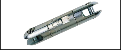
Breakaway swivels or some form of tension monitoring should be placed on the conduit to ensure that the conduit’s safe working pulling tension specified for the diameter/wall type is not exceeded. Swivels should be placed between the winch line, or drill rod, and pulling grip joined to the conduit.
If pulling multiple conduits, it is recommended to use a staggered pulling harness in conjunction with a breakaway swivel.
