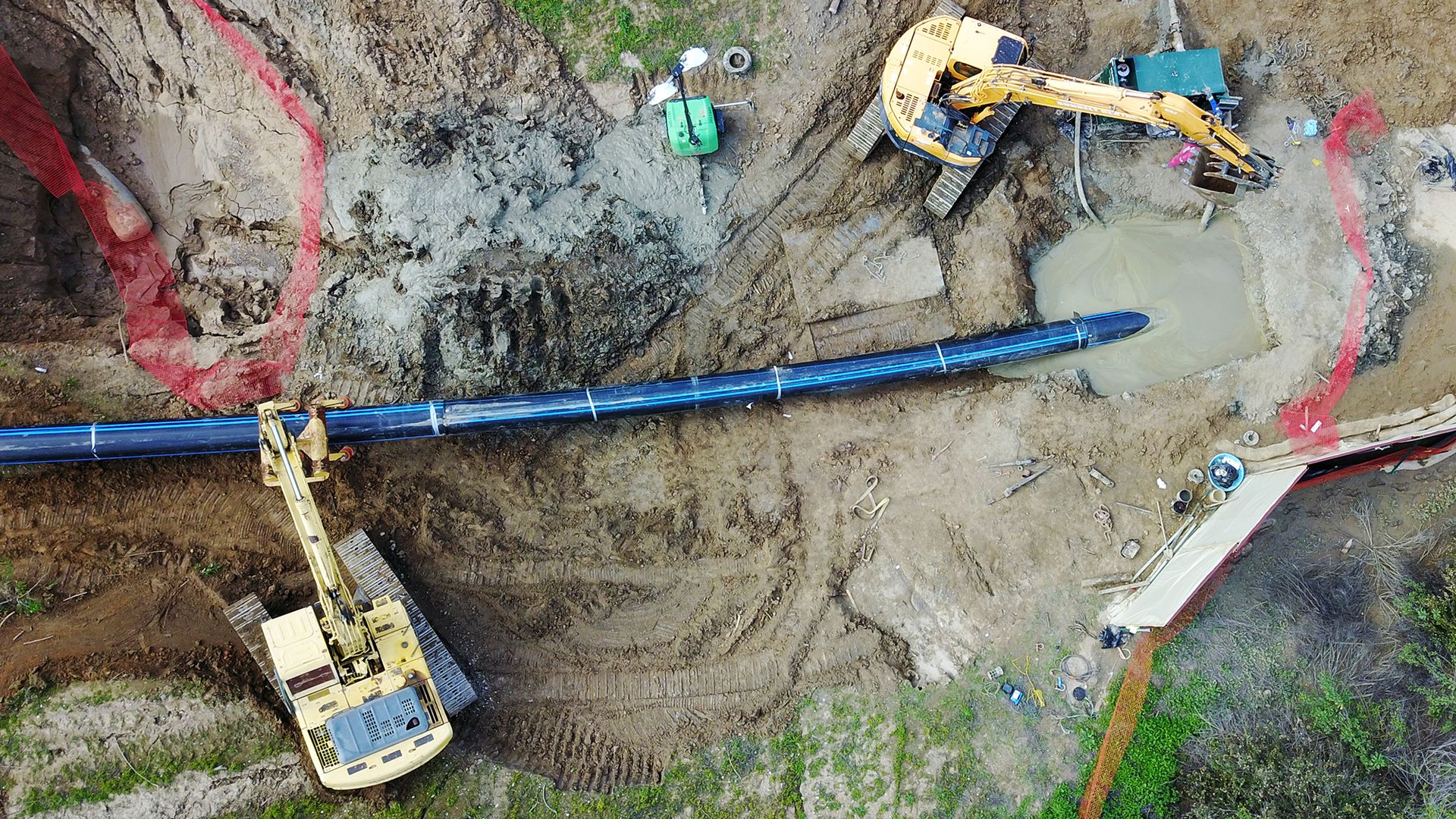
Horizontal Directional Drilling (HDD) process begins with boring a small, horizontal hole (pilot hole) under the crossing obstacle (e.g. a highway) with a continuous string of steel drill rod. When the bore head and rod emerge on the opposite side of the crossing, a special cutter, called a back reamer, is attached and pulled back through the pilot hole.
The reamer bores out the pilot hole so that the pipe can be pulled through. The pipe is usually pulled through from the side of the crossing opposite the drill rig.
Pilot Hole
Pilot hole reaming is the key to a successful directional drilling project. It is as important to an HDD pipeline as backfill placement is to an open-cut pipeline. Properly trained crews can make the difference between a successful and an unsuccessful drilling program for a utility.
Several institutions provide operator training programs, one of which is University of Texas at Arlington Center for Underground Infrastructure Research and Education (CUIRE). Drilling the pilot hole establishes the path of the drill rod (“drill-path”) and subsequently the location of the PE pipe.
Typically, the bore-head is tracked electronically so as to guide the hole to a pre-designed configuration. One of the key considerations in the design of the drill-path is creating as large a radius of curvature as possible within the limits of the right-of-way, thus minimizing curvature.
Curvature induces bending stresses and increases the pullback load due to the capstan effect. The capstan effect is the increase in frictional drag when pulling the pipe around a curve due to a component of the pulling force acting normal to the curvature.
Higher tensile stresses reduce the pipe’s collapse resistance. The drill-path normally has curvature along its vertical profile. Curvature requirements are dependent on site geometry (crossing length, required depth to provide safe cover, staging site location, etc.)
But, the degree of curvature is limited by the bending radius of the drill rod and the pipe. More often, the permitted bending radius of the drill rod controls the curvature and thus significant bending stresses do not occur in the pipe.
The designer should minimize the number of curves and maximize their radii of curvature in the right-of-way by carefully choosing the entry and exit points. The driller should also attempt to minimize extraneous curvature due to undulations (dog-legs) from frequent overcorrecting alignment or from differences in the soil strata or cobbles.
Pilot Hole Reaming
The REAMING operation consists of using an appropriate tool to open the pilot hole to a slightly larger diameter than the carrier pipeline. The percentage oversize depends on many variables including soil types, soil stability, depth, drilling mud, borehole hydrostatic pressure, etc.
Normal over-sizing may be from 1.2 to 1.5 times the diameter of the carrier pipe. While the over-sizing is necessary for insertion, it means that the inserted pipe will have to sustain vertical earth pressures without significant side support from the surrounding soil.
Prior to pullback, a final reaming pass is normally made using the same sized reamer as will be used when the pipe is pulled back (swab pass). The swab pass cleans the borehole, removes remaining fine gravels or clay clumps and can compact the borehole walls.
Drilling Mud
Usually a “drilling mud” such as fluid bentonite clay is injected into the bore during cutting and reaming to stabilize the hole and remove soil cuttings. Drilling mud can be made from clay or polymers. The primary clay for drilling mud is sodium montmorillonite (bentonite).
Properly ground and refined bentonite is added to fresh water to produce a “mud.” The mud reduces drilling torque, and gives stability and support to the bored hole.
The fluid must have sufficient gel strength to keep cuttings suspended for transport, to form a filter cake on the borehole wall that contains the water within the drilling fluid, and to provide lubrication between the pipe and the borehole on pullback. Drilling fluids are designed to match the soil and cutter.
They are monitored throughout the process to make sure the bore stays open, pumps are not overworked, and fluid circulation throughout the borehole is maintained. Loss of circulation could cause a locking up and possibly overstressing of the pipe during pullback.
Drilling muds are thixotropic and thus thicken when left undisturbed after pullback. However, unless cementitious agents are added, the thickened mud is no stiffer than very soft clay. Drilling mud provides little to no soil side-support for the pipe.
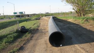
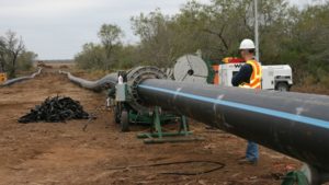
Pullback
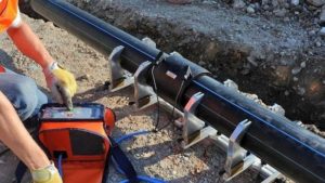
The pullback operation involves pulling the entire pipeline length in one segment (usually) back through the drilling mud along the reamed-hole pathway. Proper pipe handling, cradling, bending minimization, surface inspection, and fusion welding procedures need to be followed.
Axial tension force readings, constant insertion velocity, mud flow circulation/exit rates, and footage length installed should be recorded. The pullback speed ranges usually between 1 to 2 feet per minute.
Mini-Horizontal Directional Drilling
The Industry distinguishes between mini-HDD and conventional HDD, which is sometimes referred to as maxi-HDD. Mini-HDD rigs can typically handle pipes up to 10” or 12” diameter and are used primarily for utility construction in urban areas, whereas HDD rigs are typically capable of handling pipes as large as 48”diamter.
These machines have significantly larger pullback forces ranging up to several hundred thousand pounds.
General Guidelines
The designer will achieve the most efficient design for an application by consulting with an experienced contractor and a qualified engineer. Here are some general considerations that may help particularly in regard to site location for PE pipes:
- Select the crossing route to keep it to the shortest reasonable distance.
- Find routes and sites where the pipeline can be constructed in one continuous length; or at least in long multiple segments fused together during insertion.
- Although compound curves have been done, try to use as straight a drill path as possible.
- Avoid entry and exit elevation differences in excess of 50 feet; both points should be as close as possible to the same elevation.
- Locate all buried structures and utilities within 10 feet of the drill-path for miniHDD applications and within 25 feet of the drill-path for maxi-HDD applications. Crossing lines are typically exposed for exact location.
- Observe and avoid above-ground structures, such as power lines, which might limit the height available for construction equipment.
- The HDD process takes very little working space versus other methods. However, actual site space varies somewhat depending upon the crossing distance, pipe diameter, and soil type.
- Long crossings with large diameter pipe need bigger, more powerful equipment and drill rig.
- As pipe diameter increases, large volumes of drilling fluids must be pumped, requiring more/larger pumps and mud-cleaning and storage equipment.
- Space requirements for maxi-HDD rigs can range from a 100 feet wide by 150 feet long entry plot for a 1000 ft crossing up to 200 feet wide by 300 feet long area for a crossing of 3000 or more feet.
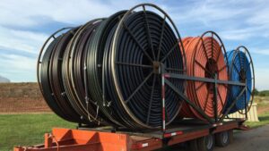
- On the pipe side of the crossing, sufficient temporary space should be rented to allow fusing and joining the PE carrier pipe in a continuous string beginning about 75 feet beyond the exit point with a width of 35 to 50 feet, depending on the pipe diameter. Space requirements for coiled pipe are considerably less. Larger pipe sizes require larger and heavier construction equipment which needs more maneuvering room (though use of PE minimizes this). The initial pipe side “exit” location should be about 50’ W x 100’ L for most crossings, up to 100’ W x 150’ L for equipment needed in large diameter crossings.
- Obtain “as-built” drawings based on the final course followed by the reamer and the installed pipeline. The gravity forces may have caused the reamer to go slightly deeper than the pilot hole, and the buoyant pipe may be resting on the crown of the reamed hole. The as-built drawings are essential to know the exact pipeline location and to avoid future third party damage.
Safety
Safety is a primary consideration for every directionally drilled project. While this chapter does not cover safety, there are several manuals that discuss safety including the manufacturer’s Operator’s Manual for the drilling rig and the Equipment Manufacturer’s Institute (EMI) Safety Manual: Directional Drilling Tracking Equipment.
Geotechnical Investigation
Before any serious thought is given to the pipe design or installation, the designer will normally conduct a comprehensive geotechnical study to identify soil formations at the potential bore sites. The purpose of the investigation is not only to determine if directional drilling is feasible, but to establish the most efficient way to accomplish it.
With this information the best crossing route can be determined, drilling tools and procedures selected, and the pipe designed. The extent of the geotechnical investigation often depends on the pipe diameter, bore length and the nature of the crossing.
Refer to ASTM F1962, Guide for Use of Maxi-Horizontal Directional Drilling for Placement of Polyethylene Pipe or Conduit Under Obstacles, Including River Crossings and ASCE MOP 108, Pipeline Design for Installation by Horizontal Directional Drilling for additional information.
During the survey, the geotechnical consultant will identify a number of relevant items including the following:
- Soil identification to locate rock, rock inclusions, gravelly soils, loose deposits, discontinuities and hardpan.
- Soil strength and stability characteristics
- Groundwater
(Supplemental geotechnical data may be obtained from existing records, e.g. recent nearby bridge constructions, other pipeline/cable crossings in the area.)
For long crossings, borings are typically taken at 700 ft intervals. For short crossings (1000 ft or less), as few as three borings may suffice. The borings should be near the drill-path to give accurate soil data, but sufficiently far from the borehole to avoid pressurized mud from following natural ground fissures and rupturing to the ground surface through the soil-test bore hole.
A rule-of -thumb is to take borings at least 30 ft to either side of bore path. Although these are good general rules, the number, depth and location of boreholes is best determined by the geotechnical engineer.
Geotechnical Data For River Crossings
River crossings require additional information such as a study to identify river bed, river bed depth, stability (lateral as well as scour), and river width. Typically, pipes are installed to a depth of at least 20 ft below the expected future river bottom, considering scour. Soil borings for geotechnical investigation are generally conducted to 40 ft below river bottom.
Summary
The best conducted projects are handled by a team approach with the design engineer, bidding contractors and geotechnical engineer participating prior to the preparation of contract documents. The geotechnical investigation is usually the first step in the boring project. Once the geotechnical investigation is completed, a determination can be made whether HDD can be used.
At that time, design of both the PE pipe and the installation can begin. The preceding paragraphs represent general guidance and considerations for planning and designing an HDD PE pipeline project. These overall topics can be very detailed in nature.
Individual HDD contractors and consultant engineering firms should be contacted and utilized in the planning and design stage. Common sense along with a rational in-depth analysis of all pertinent considerations should prevail.
Care should be given in evaluating and selecting an HDD contractor based upon successful projects, qualifications, experience and diligence. A team effort, strategic partnership and risk-sharing may be indicated.