After completion of the geotechnical investigation and determination that HDD is feasible, the designer turns attention to selecting the proper pipe. The proper pipe must satisfy all hydraulic requirements of the line including flow capacity, working pressure rating, and surge or vacuum capacity.
These considerations have to be met regardless of the method of installation. For HDD applications, in addition to the hydraulic requirements, the pipe must be able to withstand pullback loads which include tensile pull forces, external hydrostatic pressure, and tensile bending stresses, and external service loads (post-installation soil, groundwater, and surcharge loads occurring over the life of the pipeline).
Often the load the pipe sees during installation such as the combined pulling force and external pressure will be the largest load experienced by the pipe during its life.
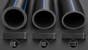
(PE pipe is classified by DR. The DR is the “dimension ratio” and equals the pipe’s outer diameter divided by the minimum wall thickness.)
Normally, the designer starts the DR selection process by determining the DR requirement for the internal pressure. The designer will then determine if this DR is sufficient to withstand earth, live, and groundwater service loads. If so, then the installation (pullback) forces are considered.
Ultimately, the designer chooses a DR that will satisfy all three requirements: the pressure, the service loads, and the pullback load.
Although there can be some pipe wall stresses generated by the combination of internal pressurization and wall bending or localized bearing, generally internal pressure and external service load stresses are treated as independent. This is permissible primarily since PE is a ductile material and failure is usually driven by the average stress rather than local maximums. There is a high safety factor applied to the internal pressure, and internal pressurization significantly reduces stresses due to external loads by re-rounding.
(One exception to this is internal vacuum, which must be combined with the external pressure.)
Design Considerations for Net External Loads
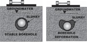
One important factor in determining what load reaches the pipe is the condition of the borehole, i.e. whether it stays round and open or collapses. This will depend in great part on the type of ground, the boring techniques, and the presence of slurry (drilling mud and cutting mixture).
If the borehole does not deform (stays round) after drilling, earth loads are arched around the borehole and little soil pressure is transmitted to the pipe. The pressure acting on the pipe is the hydrostatic pressure due to the slurry or any groundwater present.
The slurry itself may act to keep the borehole open. If the borehole collapses or deforms substantially, earth pressure will be applied to the pipe. The resulting pressure could exceed the slurry pressure unless considerable tunnel arching occurs above the borehole.
Where no tunnel arching occurs, the applied external pressure is equal to the combined earth, groundwater, and live-load pressure. For river crossings, in unconsolidated river bed soils, little arching is anticipated . The applied pressure likely equals the geostatic stress (sometimes called the prism load).
In consolidated soils, arching above the borehole may occur, and the applied pressure will likely be less than the geostatic stress, even after total collapse of the borehole crown onto the pipe. If the soil deposit is a stiff clay, cemented, or partially lithified, the borehole may stay open with little or no deformation. In this case, the applied pressure is likely to be just the slurry head or groundwater head.
In addition to the overt external pressures such as slurry head and groundwater, internal vacuum in the pipe results in an increase in external pressure due to the removal of atmospheric pressure from inside the pipe. On the other hand, a positive internal pressure in the pipe may mediate the external pressure.
When calculating the net external pressure, the designer will give careful consideration to enumerating all applied loads and their duration. In fact, most pipelines go through operational cycles that include unpressurized or being drained, operating at working pressure, flooding, shutdowns, and vacuum and peak pressure events.
As each of these cases could result in a different net external pressure, the designer will consider all phases of the line’s life to establish the design cases. In addition to determining the load, careful consideration must be given to the duration of each load. PE pipe is viscoelastic, that is, its effective properties depend on duration of loading.
For instance, an HDD conduit resists constant groundwater and soil pressure with its long-term apparant modulus stiffness. On the other hand, an HDD force-main may be subjected to a sudden vacuum resulting from water hammer. When a vacuum occurs, the net external pressure equals the sum of the external pressure plus the vacuum.
Since surge is instantaneous, it is resisted by the pipe’s short-term apparant modulus,, which can be four times higher than the long- term apparent modulus. For pressure lines, consideration should be given to the time the line sits unpressurized after construction.
This may be several months. Most directionally drilled lines that contain fluid will have a static head, which will remain in the line once filled. This head may be subtracted from the external pressure due to earth/ groundwater load. The designer should keep in mind that the external load also may vary with time, for example, flooding.
Earth and Groundwater Pressure
Earth loads can reach the pipe when the borehole deforms and contacts the pipe. The amount of soil load transmitted to the pipe will depend on the extent of deformation and the relative stiffness between the pipe and the soil. Earth loading may not be uniform. Due to this complexity, there is not a simple equation for relating earth load to height of cover.
Groundwater loading will occur whether the hole deforms or not; the only question is whether or not the slurry head is higher and thus may in fact control design. Thus, what loads reach the pipe will depend on the stability of the borehole. The designer may wish to consult a geotechnical engineer for assistance in determining earth and groundwater loads, as the loads reaching the pipe depend on the nature of the soil.
Stable Borehole – Groundwater Pressure Only
A borehole is called stable if it remains round and deforms little after drilling. For instance, drilling in competent rock (rock that can be drilled without fracturing and collapsing) will typically result in a stable borehole. Stable boreholes may occur in some soils where the slurry exerts sufficient pressure to maintain a round and open hole.
Since the deformations around the hole are small, soil pressures transmitted to the pipe are negligible. The external load applied to the pipe consists only of the hydrostatic pressure due to the slurry or the groundwater, if present.
Borehole Deforms/Collapse With Arching Mobilized
When the crown of the hole deforms sufficiently to place soil above the hole in the plastic state, arching is mobilized. In this state, hole deformation is limited. If no soil touches the pipe, there is no earth load on the pipe. However, when deformation is sufficient to transmit load to the pipe, it becomes the designer’s chore to determine how much earth load is applied to the pipe.
At the time of this writing, there have been no published reports giving calculation methods for finding earth load on directionally drilled pipes. Based on the successful performance of directionally drilled PE pipes, it is reasonable to assume that some amount of arching occurs in many applications.
The designer of HDD pipes may gain some knowledge from the approaches developed for determining earth pressure on auger bored pipes and on jacked pipes. It is suggested that the designer become familiar with all of the assumptions used with these methods.
Borehole Collapse with Prism Load
In the event that arching in the soil above the pipe breaks down, considerable earth loading may occur on the pipe. In the event that arching does not occur, the upper limit on the load is the weight of the soil prism (PE = gSEHC) above the pipe. The prism load is most likely to develop in shallow applications subjected to live loads, boreholes in unconsolidated sediments such as in some river crossings, and holes subjected to dynamic loads.
Combination of Earth and Groundwater Pressure
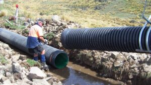
Where groundwater is present in the soil formation, its pressure must be accounted for in the external load term. For instance, in a river crossing one can assume with reasonable confidence that the directionally drilled pipe is subjected to the earth pressure from the sediments above it combined with the water pressure.
Live Loads
Wheel loads from trucks or other vehicles are significant for pipe at shallow depths whether they are installed by open cut trenching or directional drilling. The wheel load applied to the pipe depends on the vehicle weight, the tire pressure and size, vehicle speed, surface smoothness, pavement and distance from the pipe to the point of loading.
In order to develop proper soil structure interaction, pipe subject to vehicular loading should be installed at least 18” or one pipe diameter (whichever is larger) under the road surface. Generally, HDD pipes are always installed at a deeper depth so as to prevent inadvertent returns from occurring during the boring.
Performance Limits
The design process normally consists of calculating the loads applied to the pipe, selecting a trial pipe DR, then calculating the safety factor for the trial DR. If the safety factor is adequate, the design is sufficient. If not, the designer selects a lower DR and repeats the process. The safety factor is established for each performance limit of the pipe by taking the ratio of the pipe’s ultimate strength or resistance to the applied load.
External pressure from earth load, groundwater, vacuum and live load applied to the HDD pipe produces a compressive ring thrust in the pipe wall and ring bending deflection. The performance limit of unsupported PE pipe subjected to compressive thrust is ring buckling (collapse).
The performance limit of a PE pipe subjected to ring bending (a result of non-uniform external load, i.e. earth load) is ring deflection.
Viscoelastic Behavior
Both performance limits are proportional to the apparent modulus of elasticity of the PE material. For viscoelastic materials like PE, the modulus of elasticity is a time- dependent property, that is, its value changes with time under load. A newly applied load increment will cause a decrease in apparent stiffness over time. Unloading will result in rebounding or an apparent gain in stiffness.
The result is a higher resistance to short term loading than to long-term loading. Careful consideration must be given to the duration and frequency of each load, so that the performance limit associated with that load can be calculated using PE material properties representative of that time period.
The same effects occur with the pipe’s tensile strength. For instance, during pullback, the pipe’s tensile yield strength decreases with pulling time, so the safe (allowable) pulling stress is a function of time under load, and temperature.
Ring Deflection (Ovalization)
Non-uniform pressure acting on the pipe’s circumference such as earth load causes bending deflection of the pipe ring. Normally, the deflected shape is an oval. Ovalization may exist in non-rerounded coiled pipe and to a lesser degree in straight lengths that have been stacked, but the primary sources of bending deflection of directionally drilled pipes is earth load.
Slight ovalization may also occur during pullback if the pipe is pulled around a curved path in the borehole. Ovalization reduces the pipe’s hydrostatic collapse resistance and creates tensile bending stresses in the pipe wall.
It is normal and expected for buried PE pipes to undergo ovalization. Proper design and installation will limit ovalization (or as it is often called “ring deflection”) to prescribed values so that it has no adverse effect on the pipe.
Ring Deflection Due to Earth Load
Insitu soil characteristics and borehole stability determine to great extent the earth load applied to directionally drilled pipes. Methods for calculating estimated earth loads, when they occur, are given in the previous section on “Earth and Groundwater Pressure.” Since earth load is non-uniform around a pipe’s circumference, the pipe will undergo ring deflection, i.e. a decrease in vertical diameter and an increase in horizontal diameter.
The designer can check to see if the selected pipe is stiff enough to limit deflection and provide an adequate safety factor against buckling. The soil surrounding the pipe may contribute to resisting the pipe’s deflection.
Formulas used for entrenched pipe, such as Spangler’s Iowa Formula, are likely not applicable as the HDD installation is different from installing pipe in a trench
where the embedment can be controlled.
In an HDD installation, the annular space surrounding the pipe contains a mixture of drilling mud and cuttings. The mixture’s consistency or stiffness determines how much resistance it contributes. Consistency (or stiffness) depends on several factors including soil density, grain size and the presence of groundwater.
Researchers have excavated pipe installed by HDD and observed some tendency of the annular space soil to return to the condition of the undisturbed native soil. It is important to note that the researched installations were located above groundwater, where excess water in the mud-cuttings slurry can drain.
While there may be consolidation and strengthening of the annular space soil particularly above the groundwater level, it may be weeks or even months before significant resistance to pipe deflection develops.
Until further research establishes the soil’s contribution to resisting deflection, one option is to ignore any soil resistance and to use Equation 10 which is derived from ring deflection equations published by Watkins and Anderson.
Unconstrained Buckling
Uniform external pressure applied to the pipe either from earth and live load, groundwater, or the drilling slurry creates a ring compressive hoop stress in the pipe’s wall. If the external pressure is increased to a point where the hoop stress reaches a critical value, there is a sudden and large inward deformation of the pipe wall, called buckling.
Constraining the pipe by embedding it in soil or cementitious grout will increase the pipe’s buckling strength and allow it to withstand higher external pressure than if unconstrained. It is not likely that pipes installed below the groundwater level will acquire significant support from the surrounding mud-cuttings mixture and for pipe above groundwater support may take considerable time to develop.
Wall Compressive Stress
The compressive stress in the wall of a directionally drilled PE pipe rarely controls design and it is normally not checked. However, it is included here because in some special cases such as directional drilling at very deep depths such as in landfills it may control design.
The earth pressure applied to a buried pipe creates a compressive thrust stress in the pipe wall. When the pipe is pressurized, the stress is reduced due to the internal pressure creating tensile thrust stresses. The net stress can be positive or negative depending on the depth of cover.
Buried pressure lines may be subject to net compressive stress when shut down or when experiencing vacuum. These are usually short-term conditions and are not typically considered significant for design, since the short-term design stress of polyolefins is considerably higher than the long- term design stress.
Pipes with large depths of cover and operating at low pressures may have net compressive stresses in the pipe wall.
Installation Design Considerations
After determining the DR required for long-term service, the designer must determine if this DR is sufficient for installation. Since installation forces are so significant, a lower DR (stronger pipe) may be required.
During pullback the pipe is subjected to axial tensile forces caused by the frictional drag between the pipe and the borehole or slurry, the frictional drag on the ground surface, the capstan effect around drill-path bends, and hydrokinetic drag.
In addition, the pipe may be subjected to external hoop pressures due to net external fluid head and bending stresses. Furthermore, the drill path curvature may be limited by the pipe’s bending radius.
(Torsional forces occur but are usually negligible when back-reamer swivels are properly designed.)
Considerable judgment is required to predict the pullback force because of the complex interaction between pipe and soil. The ideal borehole behaves like a rigid tunnel with gradual curvature, smooth alignment (no dog-legs), no borehole collapses, nearly complete cuttings removal, and good slurry circulation.
The ideal borehole may be approached with proper drilling techniques that achieve a clean bore fully reamed to its final size before pullback. The closer the bore is to ideal; the more likely the calculated pullback force will match the actual.
Pullback Force
Large HDD rigs can exert between 100,000 lbs. to 500,000 lbs. pull force. The majority of this power is applied to the cutting face of the reamer device/tool, which precedes the pipeline segment into the borehole. It is difficult to predict what portion of the total pullback force is actually transmitted to the pipeline being inserted.
The pulling force which overcomes the combined frictional drag, capstan effect, and hydrokinetic drag, is applied to the pull-head and first joint of PE pipe. The axial tensile stress grows in intensity over the length of the pull. The duration of the pullload is longest at the pull-nose. The tail end of the pipe segment has zero applied tensile stress for zero time.
The incremental time duration of stress intensity along the length of the pipeline from nose to tail causes a varying degree of recoverable elastic strain and viscoelastic stretch per foot of length along the pipe. The DR must be selected so that the tensile stress in the pipe wall due to the pullback force, does not exceed the permitted tensile stress for the pipe material.
Increasing the pipe wall thickness will allow for a greater total pull-force. Even though the thicker wall increases the weight per foot of the pipe, the pullback force within the bore itself is not significantly affected by the increased weight. Hence, thicker wall pipe generally reduces stress. The designer should carefully check all proposed DR’s.
Frictional Drag Resistance
Pipe resistance to pullback in the borehole depends primarily on the frictional force created between the pipe and the borehole or the pipe and the ground surface in the entry area, the frictional drag between pipe and drilling slurry, the capstan effect at bends, and the weight of the pipe. Filling the pipe with fluid significantly reduces the buoyancy force and thus the pulling force.
PE pipe has a density near that of water. If the pipe is installed “dry” (empty) using a closed nose-pull head, the pipe will want to “float” on the crown of the borehole leading to the sidewall loading and frictional drag through the buoyancy-per-foot force and the wetted soil to pipe coefficient of friction. Most major pullbacks are done “wet”.
That is, the pipeline is filled with water as it starts to descend into the bore (past the breakover point). Water is added through a hose or small pipe inserted into the pullback pipe.
Note: The buoyant force pushing the empty pipe to the borehole crown will cause the PE pipe to “rub” the borehole crown. During pullback, the moving drill mud lubricates the contact zone. If the drilling stops, the pipe stops, or the mud flow stops, the pipe – slightly ring deflected by the buoyant force – can push up and squeeze out the lubricating mud.
The resultant “start-up” friction is measurably increased. The pulling load to loosen the PE pipe from being “stuck” in the now decanted (moist) mud can be very high. This situation is best avoided by using thicker (lower DR) pipes, doing “wet” pulls, and stopping the pull only when removing drill rods.
Capstan Force
For curves in the borehole, the force can be factored into horizontal and vertical components. Huey et al. shows an additional frictional force that occurs in steel pipe due to the pressure required by the borehole to keep the steel pipe curved. For bores with a radius of curvature similar to that used for steel pipe, these forces are insignificant for PE pipe.
For very tight bends, it may be prudent to consider them. In addition to this force, the capstan effect increases frictional resistance when pulling along a curved path. As the pipe is pulled around a curve or bend creating an angle, there is a compounding of the forces due to the direction of the pulling vectors.
Tensile Stress During Pullback
The maximum outer fiber tensile stress should not exceed the safe pull stress. The maximum outer fiber tensile stress is obtained by taking the sum of the tensile stress in the pipe due to the pullback force, the hydrokinetic pulling force, and the tensile bending stress due to pipe curvature.
During pullback it is advisable to monitor the pulling force and to use a “weak link” (such as a pipe of higher DR) mechanical break- away connector or other failsafe method to prevent over-stressing the pipe.
The axial tensile stress due to the pulling force should not exceed the pipe’s safe pull load. As discussed in a previous section, the tensile strength of PE pipe is load-rate sensitive. Time under load is an important consideration in selecting the appropriate tensile strength to use in calculating the safe pull load.
During pullback, the pulling force is not continually applied to the pipe, as the driller must stop pulling after extracting each drill rod in order to remove the rod from the drill string. The net result is that the pipe moves the length of the drill rod and then stops until the extracted rod is removed. Pullback is an incremental (discrete) process rather than a continuous process.
The pipe is not subjected to a constant tensile force and thus may relax some between pulls. A one-hour apparent modulus value might be safe for design, however, a 12-hour value will normally minimize “stretching” of the pipeline.
External Pressure During Installation
During pullback it is reasonable to assume that the borehole remains stable and open and that the borehole is full of drilling slurry. The net external pressure due to fluid in the borehole, then, is the slurry head. This head can be offset by pulling the pipe with an open nose or filling the pipe with water for the pullback.
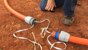
However, this may not always be possible, for instance when installing electrical conduit. In addition to the fluid head in the borehole, there are also dynamic sources of external pressure:
- If the pulling end of the pipe is capped, a plunger action occurs during pulling which creates a mild surge pressure. The pressure is difficult to calculate. The pipe will resist such an instantaneous pressure with its relatively high short- term modulus. If care is taken to pull the pipe smoothly at a constant speed, this calculation can be ignored. If the pipe nose is left open, this surge is eliminated.
- External pressure will also be produced by the frictional resistance of the drilling mud flow. Some pressure is needed to pump drilling mud from the reamer tool into the borehole, then into the pipe annulus, and along the pipe length while conveying reamed soil debris to the mud recovery pit. An estimate of this short term hydrokinetic pressure may be calculated using annular flow pressure loss formulas borrowed from the oil well drilling industry. This external pressure is dependent upon specific drilling mud properties, flow rates, annular opening, and hole configuration. This is a short-term installation condition. Thus, PE pipe’s short-term external differential pressure capabilities are compared to the actual short-term total external pressure during this installation condition.
Under normal conditions, the annular-flow back pressure component is less than 4-8 psi.
Bending Stress
HDD river crossings incorporate radii-of-curvature, which allow the PE pipe to cold bend within its elastic limit. These bends are so long in radius as to be well within the flexural bending capability of SDR 11 PE pipe which can be cold bent to 25 times its nominal OD (example: for a 12” SDR 11 PE pipe, the radius of curvature could be from infinity down to the minimum of 25 feet, i.e., a 50-foot diameter circle).
Because the drill stem and reaming rod are less flexible, normally PE can bend easily to whatever radius the borehole steel drilling and reaming shafts can bend because these radii are many times the pipe OD. However, in order to minimize the effect of ovaling some manufacturers limit the radius of curvature to a minimum of 40 to 50 times the pipe diameter.
The tensile stress due to bending is included in the calculations.
Thermal Stresses and Strains
HDD pipeline crossings generally become fully restrained in the axial direction as progressive sedimentation and soil consolidation occur within the borehole. The rate at which restraint occurs depends on the soil and drilling techniques and can take from a few hours to months. This assumption is valid for the vast majority of soil conditions, although it may not be completely true for each and every project.
During pipe installation, the moving pipeline is not axially restrained by the oversize borehole. However, the native soil tends to sediment and embed the pipeline when installation velocity and mud flow are stopped, thus allowing the soil to grip the pipeline and prevent forward progress or removal.
Under such unfortunate stoppage conditions, many pipelines may become stuck within minutes to only a few hours. The degree to which the pipeline will be restrained after completed installation is in large part a function of the sub-surface soil conditions and behavior, and the soil pressure at the depth of installation.
Although the longitudinal displacement due to thermal expansion or contraction is minimal, the possibility of its displacement should be recognized. The PE pipe should be cut to length only after it is in thermal equilibrium with the surrounding soil (usually overnight). In this way the “installed” versus “operating” temperature difference is dropped to nearly zero, and the pipe will have assumed its natural length at the existing soil/water temperature.
Additionally, the thermal inertia of the pipe and soil will oppose any brief temperature changes from the flow stream. Seasonal temperature changes happen so slowly that actual thermally induced stresses are usually insignificant within PE for design purposes.
Torsion Stress
A typical value for torsional shear stress is 50% of the tensile strength. Divide the transmitted torque by the wall area to get the torsional shear stress intensity. During the pullback and reaming procedure, a swivel is typically used to separate the rotating cutting head assembly from the pipeline pull segment.
Swivels are not 100% efficient and some minor percent of torsion will be transmitted to the pipeline. For thick wall PE pipes of SDR 17, 15.5, 11, 9 and 7, this torsion is not significant and usually does not merit a detailed engineering analysis.

