With cable-in-conduit products (CIC), the cable comes pre-installed in the duct. Where not previously installed or where additional cables may be desired, installing cables in conduit or innerduct can be accomplished in a number of ways. These include:
- Pulling cables into the conduit using a pull line or rope with puller
- Blowing cable into the conduit using specialized equipment that pushes the cable in conjunction with a high volume jet of air to pull or help propel the cable.
Placement Planning
Curvature in the conduit run is the greatest deterrent to long pulls. Some curvature is unavoidable due to path layout, e.g. elevation changes, direction changes, etc. On the other hand, sloppy installation techniques can introduce more curvature than would otherwise be planned.
For example, open trench work without proper tensioning and bedding can lead to installations that severely limit cable placement. Equations for calculation of accumulated frictional drag have been derived for pulling in cables and can be found on the worldwide web or the cable manufacturer’s literature.
These calculations are comprised of multiple combinations of straight sections and sweeps added together for estimating the total pulling load placed on the cable in a conduit section to be pulled end to end. If the cable has appreciable weight, the transition to sweep up or sweep down in any direction results in significant differences.
Additional consideration should be given to multiple conductor power cables, certain combinations of cable multiples and free volume result in jamming configurations. Push-blow techniques are also greatly affected by friction. Pre- lubricated ducts, or very light applications of silicone emulsions, produce the best results.
Techniques that predominantly rely on air to accelerate the cable work best with lightweight cables. As cable weight increases, systems with greater pushing power and piston seals provide improved performance.
A split insert is two halves of a metal fitting that seals between the cable and the conduit. It also seals between the conduit and the blowing machine within the chamber where the air is to be injected. Insert sizing is sized for the conduit/cable sizes to be installed using the air-assisted or push-blow installation methods.
In pulling cables, a greater free volume in the conduit is better and maximum fill ratios based on cable and duct diameters are around 60 percent. Conversely, maximum fill ratios in air-assisted and push-blow installations are closer to 75 percent fill and the minimum is approximately 50%.
These parameters minimize axial movement of the fiber cable, which increases frictionally generated stress, while the upper bound limit promotes efficient airflow through the conduit. Placement planning for fiber cable installation is critical because the cable lengths are so long.
Typically, one would locate a point along the route possessing similar accumulated frictional drag in either direction. Part of the cable is then installed to one end of the run, then the cable is laid out in a figure-8 to recover the opposite free end.
The free end is then installed into the other end of the run. It is not uncommon to place 3,000 to 6,000 feet over any given span, and to gang placement equipment at mid-assist intervals along the path to deliver over 20,000 feet continuously in one direction.
Using proper combinations of conduit design, installation method, lubrication and placing equipment, it is possible for crews to install over 40,000 feet of cable per day.
Pulling Cable into Conduit
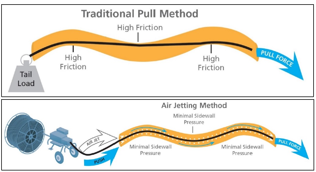
The traditional method of installing cables in conduit, particularly power cables, has been to attach a pull rope, or line, to the cable and pull the cable into the conduit using cable pulling equipment. This placement method requires pulling equipment to do the actual pulling, to apply lubricants to reduce friction, and devices that measure the amount of tension being applied to the cable.
Pull ropes/tapes are available with sequential footage marks. This type of tape is useful in determining the progress of the cable pull. Empty conduit would require a pull line to be installed. This is accomplished by blowing/vacuuming a pull line directly or blowing a lightweight line through the conduit using compressed air.
If a lightweight line is used then this line is typically used to haul a pull line or a winch line into the conduit to pull the cable. A pulling mechanism with a take-up reel is used to haul the pull line with the cable attached. The puller should have a calibrated apparatus to monitor the amount of tension being placed on the cable during the pull.
This device is extremely critical for fiber and coax cables, which are highly sensitive to tensile forces during the pull. Check with the cable manufacturer to determine the maximum amount of tension a specific type of cable can safely withstand.
Conduit may also be supplied with a pre-installed pull line/tape. This line is typically either a round twisted rope or a flat woven tape. These pull lines come in a wide variety of tensile strengths that range from 500 – 6,000 lbf (1,000, 1,250 and 2,500 lbf pulling tapes are typical). Pull lines are also available pre-lubricated to reduce friction.
When the cable is attached to the pull line, it is recommended that a swivel attachment be used between the two. This swivel will allow the cable and pull line to move independently in the conduit during the pull and prevent unnecessary twisting of the cable or pull line.
Reducing friction potentially allows longer cable pulls and reduces the risk of damage to a cable during the pull. Not all cables require the use of cable pulling lubricants. Self- lubricated cable and non-lubricated cables used in conjunction with cable pulling lubricants reduce the amount of friction placed on the cable during a pull.
The use of mid-assists may be required on very long pulls. Mid-assist equipment can be as simple as a person pulling on the cable midway or it can be a capstan type device that provides a controlled amount of pulling tension to the cable to reduce the tension on the cable and increase the potential pull length of the cable.
If the conduit is in a manhole, protective devices are needed to guide the cable into the manhole and then into the conduit. These guides protect the cable from damage to the cable sheath and/or insulation.
Air-Assisted (aka Blowing and Jetting)
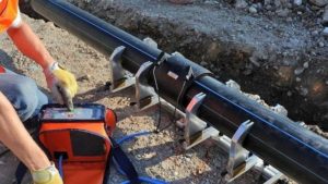
In recent years the practice of pulling cable has frequently been replaced with a newer method that uses compressed air to blow the cable into the conduit. Cable blowing requires specialized equipment that utilize high volume air compressors. There are two categories of air-assisted cable placement: Low Volume/High Pressure, and High Volume/Low Pressure.
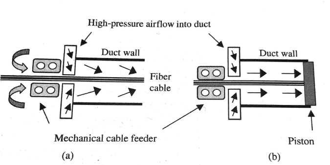
With Low Volume/High Pressure, a dart seal is attached to the end of the cable and compressed air is introduced into the duct building pressure behind the seal placed on the end of the cable, forcing the dart forward and creating a tensile pull on the end of the cable. At the same time, the cable is pushed into the conduit through a manifold seal using a tractor pusher.
The cable experiences simultaneous push and pull forces. Low Volume/High Pressure is also used for jetting into microducts minus the seal on the end of the cable. Volume is less important in the smaller microducts but high pressure is needed to overcome pressure resistance and to create enough airflow to assist propelling the lightweight microcables through the microduct.
With High Volume/Low Pressure, the cable is tractor fed into the conduit, again through a manifold seal, but this time it has no dart seal. Instead, cable progress is based on the viscous drag of high volume air alone. With these methods of cable installation, much longer lengths of cable can be placed than traditional cable pulling methods and the tension applied to the cable is significantly reduced.
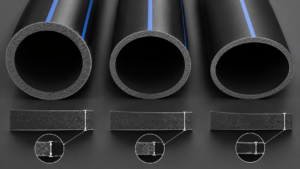
When blowing cables into conduit, the use of corrugated conduit is not recommended. Corrugated conduit causes turbulence of the air that disrupts the flow of air in the conduit reducing the distance a cable can be blown. The conduit joint/coupling needs also to be capable of withstanding the pressure of the air being introduced.
Generally, the maximum back-pressure used is in the range of 125 psi for standard conduit sizes but for microducts the pressure could reach more than 200 psi. Caution should be exercised when using compressed air to pressurize the conduit as a loose joint connection or a buildup in pressure and a sudden release can lead to injury due to the catastrophic failure of the conduit wall or connection.
Cable Installed by the Conduit Manufacturer (Cable-in-Conduit)
Some producers of conduit have the capability of installing cable while the conduit is being extruded. Each conduit producer has specific size and length limits, and it is necessary to discuss with the producer the type of cable you desire to be installed: its size, type of material and length.
Most producers can lubricate the conduit during this process to allow easy movement of the cable in the conduit for future removal and replacement if needed. Cable can be tested prior to and following installation to guarantee the integrity of the cable. Check with the conduit producer for specific information on testing the cable.
The applicable specifications for Cable-in-Conduit by the manufacturer are ASTM D3485 and UL 1990.
Coefficient of Friction in Conduit Systems
Coefficient of Friction is a critical limiting factor in determining the type and length of the cable installation. Although only an overview of cable installation is provided in this guide, this section has been made available as a background reference on frictional properties. Check with manufacturers for additional detailed installation information.
Definitions:
- Friction: the nature of interaction occurring between two surfaces. The basis of friction has its roots in the mechanical and physical-chemical makeup of the interface created by bringing together two surfaces.
- Coefficient of Friction, CoF: the ratio of the force required to move a body relative to the normal, or clamping force, acting to keep the bodies together. In the case of fiber optic cables, BellCore GR-35618 for conduit recommends a maximum of 0.20 for lubricated conduits, and GR-315519 for microducts recommends a maximum CoF of 0.15.
– Static CoF: the ratio of forces required to bring about the onset of motion between two bodies at rest with each other.
– Kinetic CoF: the ratio of forces acting on a body already in motion. It is essentially a measure of the effort required to keep the body in motion.
Friction Reduction
Friction reduction can be promoted by reducing mechanical interactions, grounding electrostatic charges, reducing polar interactions, selecting dissimilar polymers, and employing methods and mechanisms that act to dissipate heat. Although many times little can be done to control the composition of cable jacket materials, choices can be made to select friction-reducing conduit designs and lubricating mechanisms.
The use of lubricants is strongly recommended during the placement of the conduit or cable, or may be included in the manufacturing process of the conduit. Typical lubrication methods include:
- Water-soluble lubricants are available in many different forms including low viscosity free-flowing liquids, creamy consistencies, and stiff gels. Low viscosity liquids are best suited for placement of long lengths of lightweight cables, such as fiber cables. Heavier, cream-like consistencies are useful on lightweight power conductors. Stiff gels are used in vertical applications in buildings or where high sidewall loads are expected in placement of heavy power cables or innerducts.
- Polymeric water-soluble lubricants are commonly used in the field to lubricate the placement of cable, or of the conduits themselves. In this case the lubricant is applied either ahead of, or in conjunction with, the advancing cable. Water- soluble polymer chemistries include a number of different enhancements including surface wetting and cling; modification via fatty acids or their derivatives; or by inclusion of various friction-reducing oils, including silicones.
Conduits may be pre-lubricated during the manufacturing process by incorporation of lubricants directly onto the conduit inner wall or via a lubricant-modified coextruded layer. The most common type of lubricant used for this type of application is a silicone polymer, although other agents such as mineral oils, fatty acid derivatives and glycols have also found use.
Pre-lubrication finds particular value with fiber cable push-blow systems. Because the sidewall loads with these techniques are quite low compared with pulling, and the distances so great, the viscous drag contributed by water-soluble lubricants can be detrimental. The ultra-light amount of lubricants employed by factory pre-lubrication methods can be a real advantage.
The geometry of the inner surface of the conduit can also play a role in friction reduction. As the normal load increases, the CoF is found to decrease, unless the surface is damaged in such a way so as to increase the contact area, or heat is allowed to build up at a rate faster than it can be conducted away.
Ribs formed on the inner conduit wall are a common design feature to reduce friction. Rib designs can be classified as:
- Longitudinal ribbing results in a reduction of the contact surface between the cable and the conduit wall from an area of contact to a line of contact. Decreasing the area of contact under the same sidewall load results in a higher localized normal force. Within a limited range of sidewall loads, the CoF is found to go down – at least until the loading results in localized damage to the jacket sheath.
- Spiral ribbing further reduces the contact area from a line to a series of points. In addition, because the advancing cable is alternatively on and off the ribbing, there is an opportunity for cooling and re-lubrication. Constantly changing the direction of the spiral eliminates the tendency to accumulate spiral-induced torque in the cable.
- Transverse ribbing, or corrugated profiles, results in similar friction reducing geometries. However, there is a tendency for field-added lubrication to be scraped off the cable by the corrugations. In addition, the high degree of flexibility requires careful placement of the duct to reduce the buildup of friction due to additional path curvature.
Field Effects of Friction
Burn-through results when the winch line or cable develops so much frictional heat that it melts its way through the conduit wall. There are a number of factors that exacerbate this condition including: sidewall load/pressure, pull speed, conduit and pull-line coefficient of friction.
Aside from lubrication, sidewall loading/pressure may not be easily reduced; however, speed of pulling is controllable by the operator. Because PE and other thermoplastics are such good insulators, frictional heat build-up can go unchecked. Slower pull speeds combined with water-based lubricants or reduced COF pull ropes can help reduce the rate of heat accumulation.
PVC elbows are commonly used for transitions out of the underground plant. Unfortunately, PVC not only has a higher CoF than HDPE conduit but also tends to soften with the onset of heating at a much faster rate. On the other hand, HDPE conduit has a lower inherent CoF (about 0.35 vs. >0.40 for PVC) as well as a higher heat capacity due to its semi-crystalline nature.
Pull-line/rope construction also plays a significant role in burn-through. Polypropylene ropes or even PE pull-lines exhibit low CoF at low sidewall loads, but rapidly cut through both PVC conduit and PE conduit when the load increases. The tendency of these materials to soften, combined with high structural similarity to PE, limit the pull load range over which they may be used.
Polyester and polyaramid (e.g. Kevlar®) pull lines, particularly in tape form, offer greater protection from burn through. Some pull rope manufacturers provide reduced CoF constructions for this purpose.
Some of the factors that impact burn-through are:
– Sidewall loading/pressure results any time a cable or pull-line is pulled about a sweep or bend. Dividing the tension in the pull-line by the radius of the bend may approximate the magnitude of the load. Obviously, the smaller the radius, the greater the magnitude of load.
– Speed, as noted above, is a critical variable in the operator’s hands that can often spell the difference between success and failure. Speeds that are too low can result in a lot of mechanical interaction, whereas an excessively high-speed results in heat build-up.
– Compatibility (of the pull line and conduit material), in conjunction with high sidewall loading/pressure, can be a problem – not only for higher relative friction, but also is a key determinant in burn-through.
– Contamination with inorganic soils roughens or damages the surfaces of both conduit and cable jacket and increases the mechanical interaction between them. In addition, the embedment of small particles increases hydrogen bonding with water that may be in the conduit, further enhancing the interaction of jacket with conduit.
Cable-Air Installations
Cable-air installations, in which air is used in pre-installed ducts, are referred to by several different names; HASB (High Air Speed Blown) cable or cable jetting, and Air- Assisted installation or Push-Pull installation. These installation methods are divided into two types or methods:
- Cable jetting or HASB – A method for installing cable in pre-installed duct utilizing a balance between a low strain pushing force and high-speed air flow along the cable outer surface. Also known as push/blow. With this method there is virtually no pulling force at the cable end as the drag forces that move the cable are distributed equally along the entire length of the cable thereby eliminating traditional pulling forces at the cable-end. This method allows for virtually stress-free installations and is very efficient in ducts where multiple bends and undulations are present.
- Push-Pull or Air-Assisted Installation – an air capturing device (parachute, carrier or piston) is attached to the cable end. With this method the mechanical pusher forces the cable into the duct where air is captured at the cable-end creating a pulling force on the cable. Pulling forces exerted are less than those when winching but significant enough to allow for friction between the cable jacket and duct inner wall where bends are present which will typically slow or reduce speed and/or distance. This method is most efficient where duct runs are relatively straight and less efficient where bends and undulations are present.
Phases of a Successful Cable Air Installation
The following subsections break the cable-air installation into the primary steps of:
- Preparation
- Machine selection, setup & crash test
- Cable-duct fill ratio
- Air testing the duct
- Lubricating the duct
Preparation
A site survey and/or review of a workprint of the installation should be reviewed by the project owner and the cable installation company (if not one and the same) to determine overall lengths to be installed and distances between manholes/handholes for equipment placement.
These will also determine splice points and slack loop locations. It should be determined, if not already known, that the duct is properly spliced with air-tight couplers and whether there are any “open” points or problem areas in the duct route to be anticipated.
Cable reels should also be checked to ensure that sufficient lengths are available for the job as designed and that the proper cable type and fiber count is per specification. Installing the wrong cable can be a costly mistake.
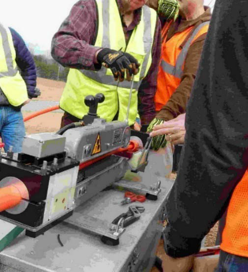
Prior to set-up of the blowing equipment, ensure that air compressors are sufficiently sized for the duct into which the cable will be installed. Also ensure that all personnel have proper safety equipment (e.g. safety glasses, ear protection, hard hats and vests) and are properly trained in the use of blowing equipment and air compressors by the manufacturer and/or suppliers of the equipment.
General Air Compressor Size Recommendations for OSP Ducts & Cable Installations
| Duct ID (inch) | Capacity (CFM) | Pressure Range (psi) |
| 0.625 – 1.00 | 185 | 100 – 175 |
| 1.00 – 1.25 | 250 | 100 – 175 |
| 1.25 – 1.50 | 375 | 100 – 175 |
| 1.50 – 2.00 | 450 | 100 – 175 |
| 2.00 | 600 – 750 | 100 psi |
Note: Pressure ranges are general recommendations only. Consideration must be given to the condition and integrity of the duct system and couplers used in the duct system. DO NOT exceed operating pressures recommended by the manufacturer of cable-air installation system or the duct manufacturer.
Air compressor requirements for microcable/microduct installations require significantly lower capacity ratings (85 to 200 CFM) at higher pressures as designated by the equipment manufacturer, e.g. 85 CFM @ 230 psi for a 7 mm microcable installed in a 12.7/10 mm microduct. Follow the specific duct and equipment manufacturer recommendations.
Machine Selection
There are many different machine models available for a variety of cable-air installations, inside plant (ISP) and outside plant (OSP) alike, covering fiber/cable diameters as follows:
- Air-Blown Fiber (ABF): <1 mm OD
- Microcable: 1 mm to 12 mm OD
- Standard Outside Plant: cables ranging from 3 mm to 36 mm OD
Due to this vast range of fiber/cable sizes, no one machine is suitable for all types of installations. The various machine models are also designed for specific size ducts or inner ducts commensurate with fiber/cable sizes listed above as follows:
- ABF Tubes/Ducts: 3 to 7 mm OD for cables <1 mm
- Microducts: 5 to 27 mm OD for cables 1 to 8 mm
- Outside Plant (OSP) Ducts: ¾ to 2.0 in. ID or 1.05 to 2.375 in. OD
- Outside Plant (OSP) Cables: 0.40 to 1.40 in. OD
Note: Some cable manufacturers designate cables up to 12 mm as microcables
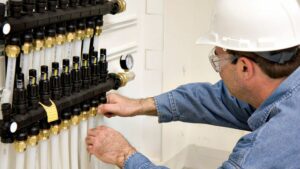
Machine Set-Up
All brands of jetting and blowing equipment are slightly different; however, they are all designed to fit multiple duct and cable sizes or outer diameters. Selecting the correct duct and cable inserts whether for OSP, ISP or microducts is important.
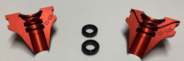
OSP or Inner Duct Insert Selection
It is extremely important to properly measure both duct and cable diameters. Not having the proper size insert to perform the installation can result in a costly delay. It is important to note that standard OSP ducts, although referred to by their inner diameter, must be fitted to the outer diameter of the duct, i.e., a 1¼ in.
SDR rated duct may have an inner diameter (ID) of 1.25 in. / 31.75 mm, but it is the outer diameter (OD) of 1.66 in. / 42 mm to which the machine’s duct insert must be fitted. To clarify, what is referred to as an inch and a quarter duct does not dictate the correct insert and selection. Always measure the OD of the duct to be fitted, otherwise a massive blow-out or leak is probable.
Microduct Insert Selection
As some microducts were designed to be installed into innerduct or OSP ducts, they are referred to by their outer diameter rather than inner diameter. Being referred to by their OD helps to determine the fill ratio inside of the larger protective duct’s inner diameter.
This makes the insert selection easier since the OD of the microduct matches exactly to the size/number on the duct insert, i.e., 12 mm microduct is fitted into a 12 mm insert.
Cable Insert Selection
Cables may be identified by fiber count or outer diameter. They are fitted by outer diameter. When jetting or blowing cables, the fiber count is NOT significant to the operator when choosing the cable insert. All that is important is that the OD of the cable must match the proper cable insert.
Most cable inserts cover a small range of cable diameters to which various size cable seals are available for a precise fit. For example, a 0.75 in. / 19.05 mm OD cable requires an 18 – 22 mm range insert. To fit this cable properly a #20 mm seal is selected, which is slightly larger than the 19.05 mm cable.
The seal selected is always slightly larger than the cable OD to channel airflow properly but not bind on the cable creating friction. A seal too tight creates friction and can inhibit production, whereas a seal too large (over 1.5 mm larger than the cable OD) can cause air loss which will also inhibit production.
Finally, all other sealing materials must be in place in the air chamber and the machine should be clean and all moving parts properly lubricated. The proper sized drive, rollers or tracks must be selected and tensioned properly.
Crash Testing
Prior to beginning any cable-air installation, it is recommended to perform a “crash test.” A crash test is used to determine the maximum push force allowable on any cable and duct combination to avert any operator error in over- driving or damaging a fiber cable on the actual job due to a manual operator error in exerting excessive push forces.
The crash test is performed with a short piece (10-15 ft) of the subject cable and duct. Although some machines are designed with auto safety shut-off mechanisms, it is always a good idea to pre- determine the maximum limits of push force. This test will instruct operators not to exceed push force limits required for any given cable installation and is the best insurance against potential on-site fiber damage that can be very disruptive and expensive.
Consult the manufacturer of your equipment for detailed instructions on performing a crash test.
Note: The smaller the fill ratio (cable OD to duct ID ratio), or with the installation of small cables in large ducts, the greater the risk of cable damage from excessive push force. This is especially true with dielectric, non-armored cables.
Cable-Duct Fill Ratios
The optimum OSP cable-to-duct fill ratio is 2:1, i.e., a cable with an outer diameter of 0.50 in. would have optimum placing performance in an inner duct with an inner diameter of 1.0 in. or 50% fill. As the outer diameter of the cable is increased in the 1.0 in. ID duct, the installation performance will tend to decrease in terms of relative speed and distance.
As also mentioned previously, there are many other performances affecting variable such as cable stiffness, weight, etc., but, as a rule, as the cable diameter increases the performance will decrease. As fill ratios exceed 80%, a rapid decrease is usually seen in performance.
Microcables in microducts typically have a slightly higher fill ratio than OSP cable in innerduct installations. Since the introduction of microcable/microduct technology around 1999, most cable manufacturers began producing microcables with fill ratios rising from 50% to near the 65% range.
This was somewhat dictated by the necessity to install as many microducts as possible into the protective inner duct for economic maximization. Sometimes maximizing the number of microducts adversely affected the inner diameter of the microducts which created the higher fill ratio.
That said, higher fill ratios with microduct is common and unless unusually high, performance tends to be acceptable.
Installing Microducts into Outside Plant Innerducts or Protective Ducts
Microducts, from 7 – 27 mm outer diameter, are designed to be jetted or blown, not pulled if placing over longer distances. Due to their smaller outer diameter, excessive pull tensions can more easily be reached causing damage. Typically, microducts that are pulled should be pulled over shorter distances to avoid damaging the microducts during installation.
Most microducts have a tensile strength rating of between 50 – 450 lbf so pulling tensile loads need to be carefully monitored. Microducts < 18 mm must be pressurized to approximately 100 psi to provide improved resistance to the compressive loading of the pusher’s conveyance belts for better pushing performance.
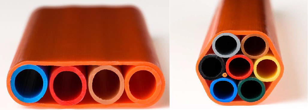
When jetting into innerducts, single microducts or bundles of microducts may be installed. If multiple microducts (bundles) are to be installed in a single innerduct, the jetting/blowing equipment requires special tracks and inserts to perform this special function.
Cable installation crews need special training for this application. Contact your cable installation equipment provider for proper instruction in safely installing and handling these microducts.
Alternatively, there are pre-bundled microduct products available in the market that are already incased in an outer HDPE sheath. All that is necessary is installation of the microcables into each individual microduct making up the oversheathed microduct bundle.
The oversheathed multi-duct can be bored (HDD), plowed or trenched. Additionally, it can be pulled into a conduit with a pull line, or a rod can be pushed through the end of the conduit and then the over-sheathed product pulled back. It should be noted that oversheathed units themselves, under 1.40 in. in diameter may be installed with a cable air system in ducts 2 in. ID or smaller.
The Installation – Air Testing the Duct
Prior to installing the cable, the duct should be air tested to be sure there are no leaking or improperly assembled couplers within the duct route. Test each duct section by putting air on the system and assessing air loss by observing the air pressure gauge on the machine and/or feeling the air at the exit end of the duct section.
Low air pressure gauge measurements on duct sections over 1,000 ft or more indicate probable air loss. Little or no air velocity at the duct end indicates air loss as well. The air should be allowed to run for several minutes to determine pressure/flow loss and to detect if there is any water or debris in the duct system.
The next step is to introduce a foam spreader or plug into each duct run. This will help to dislodge any water and/or debris. If water is present, continue to blow foam spreaders through the duct until the water is only a fine mist at the duct-end before starting the cable install.
Safety Note: Be sure the duct open end is clear and routed in a way such that it is aimed safely away from any person or object that might incur damage as a result of the expulsion of high velocity, high-pressure air, debris and/or water.
Lubricating the Duct
It is always recommended to use cable jetting or blowing lubricants as it will insure the best co-efficient of friction reduction for the installation regardless of the type of material of which the duct is made. Maximum CoF values are 0.2 for conduit and 0.15 for microducts. Any values above this will incrementally reduce the speed and performance of the cable installation.
Follow the lubricant manufacturer’s instructions for the quantity of lubricant to be used (depending upon the ID of the duct) followed by a foam spreader. The jetting lubricant can also be dispensed with an automatic lubricating device as offered by some equipment manufacturers.
Important Note: NEVER use PULLING lubricants with cable air installations. Air will turn the pulling lubricant into a sticky friction generating material. Use lubricants specifically formulated for air blown fiber installation.
The Cable Installation
In most cases a few hundred feet of cable may be installed mechanically, without air, in the lubricated duct to help determine a reasonable installation speed, prior to adding air into the duct system. Typically, as the cable begins to slow, the air valve is opened slightly and the cable speed will increase.
The operator monitors the speed, distance, push-force, and air pressure making adjustments to push force and air pressure commensurate with the equipment manufacturers training program and instructions. The specific manufacturer’s instruction for the product should always be followed.
In the instance of air loss, a coupler failure, compressor, or drive system failure immediately stop the operation and notify all parties of the stop. Correct the problem and safely resume the operation.

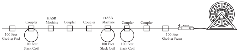
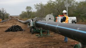
Cascading (Use of Multiple Placing Units)
Cascading is the usage of several jetting/blowing machines in series for the purpose of installing extremely long lengths of cable. The average distance under normal conditions for one machine is approximately 3,500 to 5,000 ft.
This number can vary depending upon many variables. An example of cascading effectively would be the use of 3 machines to install a 15,000 ft reel of cable in one section with no splices except at cable ends. Cascading allows for production that was unheard of when pulling cables. There are cases of over 100,000’ of cable being installed in one day by one crew with three (3) machines.
Placing Slack Coils
Slack coils, or slack loops, may be placed very quickly using the cable-air method compared to pulling slack loops where the cable to be stored had to be carried with the pullers from hole to hole.
The cable-air method for this process is very simple:
- The cable is jetted/blown to the end of the section leaving enough at the end for a splice, usually 50 to 100 ft.
- The duct is opened by removing a split coupler at the manhole/handhole closest to the end of the run where a slack coil is desired.
- The installation resumes at a slow speed until the desired amount of cable is coiled at that location and stored for a future splice.
- If more slack coils are desired, the operation continues to move back toward the cable reel end of the job following the same process.
Additionally, by using split couplers, it is possible to return and open the conduit at those junctures for installing slack loops. Slack loops of from 50 to 100 feet are frequently placed at intermediate access locations, where a full cable splice is not required. Slack loops are placed at locations where only some of the fibers in a cable are to be accessed.

Variables and Parameters Affecting Installation Lengths
There are many factors that can affect installation distances. Some of which are controllable and some which are not. Some manufacturers offer software programs that, with proper data input for the cable installation project, can estimate achievable distances.
Factors Affecting Installation Length for Cable Jetting
| Cable Outer Diameter | Cable Weight |
| Cable Stiffness | Intrinsic Cable Curvature |
| Duct Inner Diameter | Coefficient of Friction |
| Undulation Amplitude | Undulation Period |
| Installation Method | Compressor Volume and/or Pressure |
| Compressor Capacity | Pushing Unit |
| Pulling Support | Number of Curves |
| Horizontal Trajectory | Bundle |
| Resident Cables in Conduit | Air Temperature |
The programs will calculate a distance achievable. The only parameters not listed that can have a significant effect on the outcome are heat and humidity. There is currently no viable way to calculate this factor, as there are many variables within these parameters that are unknown until time of the actual installation.
There are, however, some cable installation devices that have this capability ‘on-board’ the device to be used at the installation site.
Note: Compressed air can contribute significant heat during installation. For this reason, it is an advisable practice, especially in warmer climates, to utilize an air cooler for cooling the air temperature prior to injection into the conduit.
Maintenance
Maintaining the good working condition of jetting/blowing equipment is imperative. This ensures that all mechanical working parts are clean and lubricated, which reduces friction inherent in the machine and is just as important as cleaning and lubrication inside the duct.
A machine that is binding-up will overheat thereby reducing performance. A dirty machine will also introduce contaminants into the air chamber causing the cable seals to bind restricting airflow resulting in overheating of the motors. Jetting units should be pressure washed and lubricated on a regular basis to provide optimum performance.
Summary
There are many duct and cable installation types and techniques available for “Enterprise” (i.e. ISP), or OSP installations. HASB and Push-Pull installations are the methods of choice, proven by a 25-year experience model as the safer method of installing fiber due to the minimal tensile stresses and the increased speed of installation.