Conduit can be joined by a variety of heat fusion and mechanical methods. Since conduit does not experience any long-term internal pressure and acts only as a pathway for power or other cables, the owner of the system may be tempted to neglect the importance of specifying effective couplings.
However, an integral part of any conduit system is the type and quality of joining method used. Proper engineering design of a system will consider the type and effectiveness of these joining techniques.
Joint Selection Considerations
The owner of the conduit system should be aware that there are joint performance considerations that affect the system’s reliability well beyond initial installation. Some of those might include:
- Pull-out resistance, both at installation and over time due to thermal contraction/ expansion and ground movement must be considered. This is critical for “blow-in” cable installations, which will exert an outward force at joints, but less so for pulling installations, which will tend to exert the opposite force. Once conduit is installed, temperature fluctuations are moderated by the surrounding soil, therefore pull-out forces due to temperature expansion/contraction are mitigated. Pull-out resistance due to expansion and contraction should not be confused with the safe pull strength required in HDD (Horizontal Directional Drilling). For HDD, either butt- or electro- fusing the joint are acceptable methods for joining the conduit if the joint is going to pulled into the bore.
- Internal pressures for “blow-in” installations are typically between 125 to 200 psi for a short period. Consider how much leakage can be tolerated without reducing the distance the cable can consistently be moved through the conduit.
- Infiltration leakage, allowing water and/or silt to enter the conduit over time, can create obstacles for cable installation and repair or in above ground installations can cause the water to freeze and compress the fiber optic cables.
- Corrosion resistance is important as conduit systems are often buried in soils exposed to and containing alkali, fertilizers, and ice-thawing chemicals, insecticides, herbicides and acids.
- Cold temperature brittleness resistance is required to avoid problems with installation and long-term performance in colder climates during installation.
General Joining Provisions
HDPE-to-HDPE joints may be made using heat fusion, electrofusion or mechanical fittings. The use of mechanical couplings are often preferred over fusion joints for diameters up to 6”. Mechanical couplings allow HDPE conduit to be joined to other junction boxes or other hardware utilized by the communication and electrical industries.
The user may choose from many available types and styles of joining methods, each with its own particular advantages and limitations. Contacting the various manufacturers is advisable for guidance in the proper applications and available styles for joining.
Mechanical Fittings
HDPE conduit can be joined by a variety of available styles of mechanical fittings, each with its own particular advantages and limitations. This section will not address these advantages or limitations but will only offer general descriptions of many of these fitting types and how they might be utilized.
Experts recommend that the user be well informed of the manufacturer’s intended applications, performance limits, and joining procedure for the particular mechanical fitting being used.
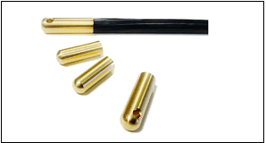
Barbed (i.e. Hydraulic Press-on) Mechanical Fittings
Barbed fittings are available in various materials and configurations for joining conduit sizes 2 in. and smaller. Installation involves pressing the fitting over the ends of the conduit to be joined using a special tool.
The inside of these fittings contains sharp, inward-facing barbs that allow the conduit to be pressed-in, yet dig into the outer surface of the conduit and resist removal when pulled. They offer excellent tensile strength for plowing operations, and, if installed correctly, have very good internal pressure characteristics for cable blowing applications.
Threaded Mechanical Fittings
Threaded mechanical fittings are available in various materials and configurations for conduit sizes 2 inch and smaller. Some are designed with sealing capabilities while others are not. The internal thread designs of these fittings are typically tapered similar to pipe threads, with a left-hand thread on one end and a right-hand thread on the other to cut thread paths on the conduit’s outer surface.
This thread design allows the operator to thread the fitting onto the ends of both conduit sections simultaneously. Some variations of threaded fittings may also be pressed on the conduit ends and used as barbed fittings. The user should consult the fitting manufacturer to determine if this alternate installation method is recommended.
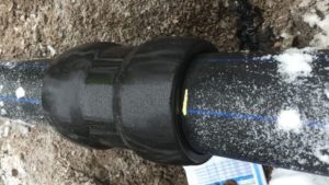
Compression Coupler
Compression couplers apply compression to the outside wall of the conduit to retain the conduit and create the joint, as shown in Figure 25. As with the other mechanical fittings, compression fittings are also available in numerous designs and for different size ranges.
While compression fittings used in the HDPE pressure piping industries, such as water or gas, typically require internal stiffeners, conduit systems typically do not as stiffeners may create obstacles for cable being blown through the conduit.
Expansion Joints
Expansion joints are designed primarily for aerial conduit installations. The primary purpose of this fitting design is to absorb thermal expansion and contraction in the conduit system created by ambient temperature changes, which can be extreme in above ground installations.
System designers should determine the number of expansion joints required based on the expansion length provided by the fitting and a calculation of the conduit’s overall thermal expansion factor for the length of above ground section being joined.
Heat Fusion
The principle of heat fusion is to heat two surfaces to a designated temperature and fuse them together by application of a force sufficient to cause the materials to flow together and mix. When fused in accordance with the manufacturer’s recommended procedure and allowed to cool to nearly ambient temperatures, the joint becomes as strong or stronger than the conduit itself in both tensile and pressure properties.
The three primary heat fusion methods used in joining PE conduit are butt, socket, and electrofusion. Butt and socket fusion joints are made using “hot irons” designed specifically for PE joining, while with electrofusion fittings heat is internally generated by electrical current applied to embedded wires within the fitting.
We recommend that users precisely follow the qualified fusion procedures established by the manufacturer of the particular heat fusion joining equipment and fittings being used.
Butt Fusion Joining
Butt fusion joints are produced without need of special fittings, using specially developed butt fusion machines, that secure, face and precisely align the conduit for the flat face hot iron fusion process. In the process, the ends of the two conduits to be joined are heated until molten and then brought together and allowed to cool creating a strong joint.
It should be noted that the butt fusion process produces an internal bead of equal or larger size than the visible outer bead that can cause restrictions and interfere with cable placement. If internal restrictions are a concern for the cable installation, alternative-joining methods may be more appropriate.
The use of a metal end cap with a rounded end will mitigate potential damage of the fiber, and normally “deflect” off any internal bead during cable installation.

Socket Fusion Joining
This technique requires the use of specially designed hot irons to simultaneously heat both the external surface of the conduit and the internal surface of the socket coupling. Specially designed hand tools are available to maintain alignment and the stab depth of the hot irons until the materials reach fusion temperature.
These tools also help secure the heated conduit end and coupling as the joint is made. Design requirements for socket fusion are provided in ASTM D2683 for fittings and in ASTM F1056 for socket fusion tools. As with butt fusion, socket-fused joints may have an internal bead that can interfere with cable placement.
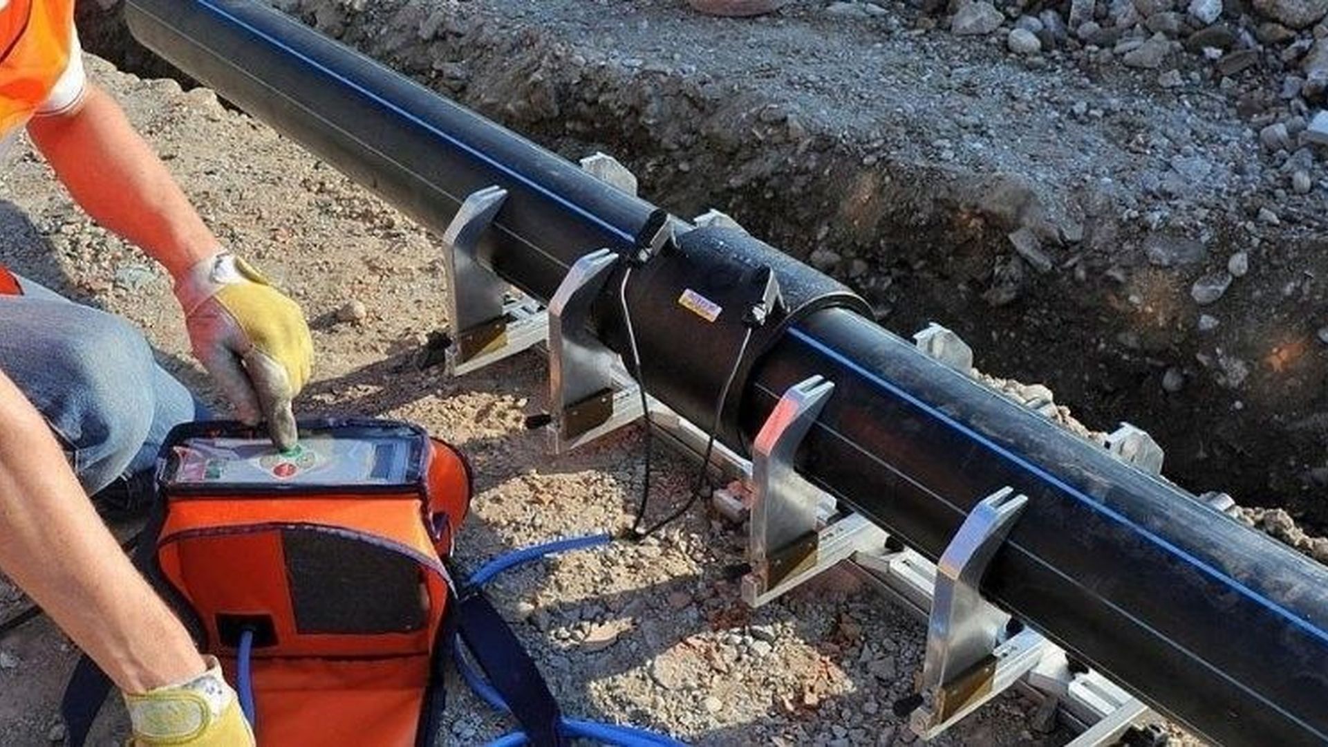
Electrofusion Joining
Electrofusion is somewhat different from the hot iron fusion method described previously, the main difference being the method by which heat is applied and the location of the resulting fusion. Electrofusion involves the use of a special electrofusion socket fitting that fits over the ends of the conduit.
The fitting has an embedded wire coil. Using a specialized external electrofusion control box, electrical current is supplied to the wire coil heating and melting the inside of the socket and the outside surface of the conduit until they fuse together.
The resulting joint is water tight and as strong as the conduit. No internal bead is generated with electrofusion.

Repair Operations
Repair fittings, as the name implies, are often designed specifically for use in repair situations. The nature of the damage will often dictate what types of joints are needed for repairs. For example, of one type of design, a clamp-on style may be preferred when damage is limited and removal of the cable for repair is not necessary.
There is a PVC tongue-and-groove semi-circle product that can be made water tight with caulking or two-part epoxy glue. However, in more severe damage situations, where new cable and conduit sections must be installed, many of the joining methods described earlier in this section may be suitable.
Ultimately, the type of repair fitting or joint installed should maintain the integrity of the conduit system, prevent infiltration and provide sufficient resistance pull-out from thermal expansion/contraction.
Special Applications
The following subsections provide an introduction to some specialized products and applications for conduit. For more information, consult with your conduit supplier.
Corrugated Duct
Corrugated conduit has properties that generally make it easier to work with in difficult and confined environments. The corrugated profile of the wall provides a greater degree of flexibility and the lack-of-memory that makes it easier to handle when used in confined spaces and other restricted environments, such as “inside plant- premise” applications.
Corrugation design (or profile) greatly affects the properties of the conduit such as compressive resistance and tensile strength. The ASTM standards that cover SIDR and SDR conduit designs do not apply to corrugated duct.
All corrugated conduit specifications are specific to the producer. Generally, a minimum ID and a maximum OD is specified. Products vary from manufacturer to manufacturer so check with the source of supply for detailed dimensional and performance specifications.
Corrugated conduit is not appropriate for use in direct buried applications because of its limited crush resistance and the difficulty of laying it in a straight path. It should not be installed using directional drilling equipment due to limited tensile strength and the fact that the corrugations will create significant friction and stretch during the pullback causing the conduit to separate.
Corrugated conduit is also not appropriate for use when cables are to be installed using air-assisted placement as it is relatively thin-walled and may not be able to handle the air pressure of air-assisted placement. The corrugations also create significant air turbulence that is counterproductive to the air-assisted placement systems and reduce the distance cables can be blown.
Multi-Cell Conduit
Multi-cell conduits are designed to meet special needs and unique job situations. There are a number of designs available to meet most of these special needs.
Multi-cell conduit can be a product that is installed as an innerduct inside of existing conduits designed to maximize the available space in a vacant or occupied conduit, or it can be a fully assembled conduit with internal conduits that, when installed, provides a multi-channel conduit without the need to install any other innerducts.
Some multi-cell designs can be direct-buried like HDPE conduit using standard installation methods (plowing or open trenching).
Armored Conduit (Rodent and Mechanical Protection)
When placing cables underground, there are occasional concerns about the need for greater mechanical protection of the cable(s) inside from the cutting and gnawing by animals. Armored Conduit is HDPE conduit that has a layer of metal for additional protection against animal attack.
Armored conduit also provides greater mechanical protection against cuts and abrasions from accidental strikes during excavation of adjacent utilities.
Conduit Building Entry Electrical Applications
Electrical/Building Code regulations vary greatly regarding the placement of conduit into a building. Codes require the use of conduit constructed of a material that is listed for use in specific building areas, and these codes limit the use of HDPE conduit beyond a specific distance after entry through an exterior wall.
The greatest variation in local code is the location of the transition from HDPE conduit to a conduit that meets the code requirement (distance from the exterior of the wall). Check your local codes for local amendments.
Premise (Flame Retardant) Comm/Data Applications
In addition to using conduit for installing fiber optic/communication cables in the underground, there are a few other very specialized applications for conduit type products. With the growing market for data communications systems and IOT (internet of things) within buildings, there has been a concurrent growth in the use of fiber optic/communication cables in buildings as well.
As these installations typically place fiber optic/communication cables in the same cable trays and vertical risers as other communications cables and electrical cables, designers and installers have been concerned about identifying and protecting these fiber optic/communication cables.
Manufacturers have responded with the development of several types of conduit for building use, or as it is known in the industry, premise wiring. Premise wiring generally uses plenum air spaces, vertical riser shafts and general- purpose areas to run cables throughout buildings.
The types of conduit developed are specific to these environments. Because premise wiring falls into areas generally thought of as locations having greater human health and safety concerns, the NFPA 70 and Underwriters Laboratories have addressed the characteristics needed by conduits to be safely used in premise wiring.
These conduit products are generally not made of HDPE due to the flame spread and smoke requirements; however, future innovations may bring acceptable HDPE-based products to this market in the future. Initial development produced the Plenum Raceway, a specialized conduit that meets more stringent Underwriters Laboratories UL 2024 requirements for minimum flame spread and smoke generation than riser rated conduit.
Plenum Raceway can be a corrugated conduit or microduct made from plastic materials that do not support flame and produces very low smoke. At this time, PVDF (polyvinylidene fluoride) is the material of choice for Plenum Raceway.
Similarly, Riser Raceway was developed for premise wiring applications to be installed in specific locations such as in riser shafts. Riser Raceway meets the Underwriters Laboratories UL 2024 requirements for vertical flame spread. The Riser Raceway requirements are lower than Plenum Raceway. Riser Raceway can also be a corrugated conduit or microduct.
General-Purpose Raceway was developed for premise wiring applications in general purpose applications. General-purpose raceway meets the Underwriters Laboratories (UL 2024) requirements for flame spread and has lower requirements than Riser Raceway.
General-purpose raceway is typically a corrugated conduit or microduct, which is currently produced from either PVC or polyamide materials. All conduit products for use in riser, plenum, or general raceway applications are required to be marked with the application specific product standard and a Listing
Mark from a nationally recognized independent certification laboratory (e.g. UL, ETL20, CSA, etc.,) to demonstrate that the product has been tested and meets the requirements for installation in the specific application. Plenum Raceways are permitted to be placed in a riser application. Plenum and Riser Raceways are permitted to be placed in a general-purpose application.
The uses of Plenum or Riser Raceways do not eliminate the use of a Plenum- or Riser-rated cable. As the use of fiber optic/communication cables in premise wiring increases there will likely be other specific needs that may generate other types of conduit for use in building wiring systems.
Inside plant microducts are now produced for premise and raceway product meeting UL 2024 standards. Fiber cable can be air blown into microduct.
Underwater Applications
The term underwater is used to describe marine, or submarine, applications. The three basic methods of placing an underwater conduit are laying the conduit on the bottom, plowing and jetting the conduit into the sub-aqueous terrain, or horizontal directional drilling under the waterway. Each method has its own unique requirements based on the type of waterway, length, environmental issues, and federal, state and local requirements.
There may be instances when all three methods will be required within the same installation. Conduit placed on the bottom of waterways should be black to prevent UV damage.
Bridge Crossing Applications
Bridge structures can range from a simple conduit placed in the bridge structure when the bridge is built to a major retrofit of an existing bridge that does not already contain a conduit or structure in place to secure a single conduit or conduits.
Bridge structures, new or old, require specially designed support systems to ensure structural integrity and meet all federal, state and local requirements. The expansion/contraction considerations with HDPE make it a less than ideal product for exposed bridge crossings.
Generally, FRP conduit (Fiberglass Reinforced Pipe) is a better alternative for bridge conduit as it has beam strength, is produced to “low smoke zero halogen” standards, and can be designed to be bullet proof.
Conduit Specific Industry Terminology & Abbreviations
| Term | Definition |
| Air Blown Fiber (ABF) | A process using compressed air and hand-sized equipment to feed low count unreinforced fiber cable into microducts, where the flow of compressed air over the fiber propels and
pulls the fiber through the conduit. See Jetting. |
| Community Antenna TV (CATV) | Cable TV service, typically offered through coaxial or fiber cable to provide service delivered from a satellite headend. |
| Cable-in-Conduit (CIC) | A product offering where the conduit is offered pre-installed with the chosen cable type. |
| Canadian Standards Association (CSA) | Canadian Standards Association is a standards organization developing and publishing standards used in
North America. CSA, a recognized laboratory, also certifies products for end-use. |
| Casing | A larger diameter pipe used to protect smaller conduits or cables when installed underneath roads, rivers or other
obstacles. |
| Coax Cable | A cable used in the cable TV industry for TV or data
transmission. |
| Conduit | A typically plastic pipe pathway used to protect fiber, power or coax cable. This term is interchangeable with “Duct”. |
| Corrugated Conduit | Conduit or pipe with a thinner wall with a corrugated profile to give it compressive strength and flexibility. |
| Dark Fiber | Dark fiber refers to unused fiber-optic cable. Often times companies lay more fiber cable, or conduit, than what is immediately needed in order to provide additional capacity for future needs. The unused capacity can be leased, sold or made available to other entities who want to establish
optical connections among their own locations. |
| Department of Transportation (DOT) | A governmental department having jurisdiction over specifications and requirements for articles used in transportation. |
| Direct Burial | A construction method of placing cable or conduit by
traditional methods into the ground(as opposed to plowing or directional drilling HDD). |
| Duct | See Conduit. |
| Environmental Stress Crack Resistance (ESCR) | Environmental Stress Crack Resistance is a measure of the long-term resistance to cracking of the polyethylene material. It can be measured through a test method that accelerates crack failure in polyethylene by inducing a
stress and placing the specimen in a surfactant at high temperatures then observing when cracking initiates. |
| Term | Definition |
| Fiber Optic Cable | A cable comprised of very thin glass fibers with unique
refractive characteristics that can be used to transmit data by a color laser initiated lightwave device. |
| Fiber-To- The-Home (FTTH) | A generic term for any broadband network architecture using optical fiber to provide all or part of the local distribution network used for connections directly to the subscriber. Frequently referred to as last
mile telecommunications. |
| FRP Conduit | Rigid conduit of fiber reinforced plastic material used most
often in bridge locations requiring greater strength or highly corrosive environments. Often specified as bullet proof. |
| General-Purpose Raceway | Conduit used inside buildings with some smoke and fire resistance. See Plenum and Riser-Raceway. |
| High Density Polyethylene (HDPE) | High density polyethylene is a durable plastic material used in the manufacture of conduit. A plastic material, composed
mostly of ethylene used in the manufacture of durable conduit. |
| Horizontal Directional Drilling (HDD) | A method of placing conduit by drilling horizontally with a steel threaded drill string (assembled pipes) that have directional change capabilities and can be guided to circumvent underground obstructions. Conduit is then attached to the daylight end of the drill string and pulled back through the borehole to provide a clear pathway for
cable to be inserted. See Maxi HDD and Mini HDD. |
| Innerduct | A smaller duct used to subdivide a larger duct or casing. |
| Inside Plant (ISP) or
/Premise (ISP) |
The communication and electrical sub structure in a
building. Raceways in this environment have special fire and smoke retardant requirements. |
| Jetting or Push Blow | A method of blowing fiber cable that employs high volume and air pressure within a conduit to float cable along with a track system to simultaneously push the fiber cable through the conduit. Also see “push/pull” method of fiber cable
placement. |
| Listing Mark | A UL, ETL, CSA or similar mark, from a nationally or internationally certifying agency used to designate conduit that was tested by a certified third-party laboratory in
accordance electrical standards defined by the National Electric Code. |
| Maxi HDD | Horizontal Directional Drilling of large diameter casings of various pipe or conduit materials in lengths in excess of
1000’. Requires extensive subsurface planning and engineering. |
| Microduct | A very small diameter polyethylene conduit (from 4mm to 27mm) used for installation of micro fiber cables. Used in FTTH applications to deliver low count fiber directly to the premises of offices or homes. Sometimes oversheathed in a package of multiple microducts to add more micro fiber
cables as additional capacity is needed. |
| Mid-Assist | A capstan (mechanical installation equipment) used to assist in extending the installation length at an intermediate location. It consists of placing cable in the middle of two
runs. |
| Mini HDD | Horizontal Directional Drilling of conduit, up to 12 inches in diameter for short lengths up to 1000 feet. This method is used with less field information and therefore uses a very conservative calculation for selection of conduit wall
thickness. |
| Term | Definition |
| Outside Plant (OSP) | Communication or power cable either buried or aerial,
providing data or power distribution system. |
| Overriding | A method of placing a microduct into a conduit currently occupied by a fiber cable to provide an additional pathway or pathways for increasing capacity. |
| Plenum Raceway | A conduit inside buildings rated for placement in a plenum airspace, typically horizontally. Plenum rated conduit has very low smoke and superior fire resistance requirements
qualifying it for use in this application. Tested in accordance with UL 2024. (see Riser Raceway). |
| PVC Conduit | A conduit produced from poly(vinyl chloride) polymer, typically provided in rigid lengths from 10 to 20 feet long. |
| Pull Line (aka Mule Pull Tape) | A polymer flat woven tape or rope typically made of polyester or polypropylene strands placed inside conduit (either during extrusion manufacturing or inserted in the
field) used to pull cable into the conduit. |
| Reaming or Backreaming | The act of widening a bore hole in a drilling operation. Backreaming is the practice of pumping in a bentonite slurry and rotating the drill string with a backreamer to widen and
form the bore hole wall. |
| Riser Raceway | Inside building conduit used in vertical shaft and other approved locations to connect communication broadband cables between floors. Riser conduit has reduced smoke
and fire spread requirements, but not as stringent as Plenum Raceway. |
| Rock Impingement | Term used to describe a rock in direct contact and impacting the outer surface of the conduit in a buried
application, potentially damaging the conduit. |
| Rodded | A fairly stiff fiberglass rod that can be pushed inside a
conduit. It can be used for proofing the integrity of a conduit’s pathway. |
| Slow Crack Growth (SCG) | A potential long-term brittle failure mode of polyethylene conduit under stress. See also ESCR. |
| Strand | Stranded high strength steel wire used to aerially support
conduit or cable between poles or other structures. |
| Supervisory Command and Data Acquisition (SCADA) | A computerized system architecture using computer and communications equipment that allows remote monitoring,
data acquisition and control of critical components in networks or infrastructure from a centralized control center. |
| Tail Loading | The amount of tension required to be placed on a conduit
being pulled from a reel, for example in an HDD application or cable into a conduit. |
| Ultraviolet (UV) Protection | Ultraviolet light/sunlight which may adversely affect plastic conduit if not adequately formulated for the duration of storage and application. HDPE conduit is can be protected from UV degradation by adding carbon black (black conduit) or other specialized additives for longer term protection of
colored conduit. |
| Viscoelastic | Viscoelastic is the property of materials that exhibit both viscous and elastic characteristics when undergoing deformation. Viscous materials, like water, resist shear flow and strain linearly with time when
a stress is applied. Elastic materials strain when stretched and immediately return to their original state once the stress is removed. |